
Every digital chip draws current in short, sudden bursts as its internal gates switch on and off millions of times a second.
A power supply sitting a few centimeters away on the board simply cannot react fast enough to follow those bursts through the trace inductance in between.
A decoupling capacitor sits right at the chip and closes that gap, releasing charge in nanoseconds so the chip never sees the voltage sag.
This guide covers how decoupling capacitors work, why placement matters as much as value, and how to choose the right values for a real circuit.
A decoupling capacitor is a small capacitor placed close to an integrated circuit's power pins that supplies instant charge during a sudden current demand, keeping the local supply voltage stable when the main power source cannot respond quickly enough.
Digital chips do not draw a steady, constant current. Every clock edge that flips a gate pulls a fast spike of current from the supply rail, then releases it just as quickly.
Left unmanaged, those spikes cause the local voltage to dip and ring, which can flip a logic level at the wrong moment or inject noise into a nearby analog circuit.
This article explains the mechanism behind decoupling, why capacitor placement can matter more than the capacitor value itself, and how to pick values that actually cover a real noise spectrum.
What Decoupling Capacitors Actually Do
A decoupling capacitor acts as a small, local charge reservoir. It stores energy while the chip is idle, then releases that energy the instant current demand spikes.
Because the capacitor sits right next to the power pins, the electrical path is short. A short path means low inductance, and low inductance means the stored charge can leave the capacitor fast enough to match the chip's switching speed.
Without it, that same current would have to travel all the way back to the power supply and back again, a round trip far too slow for a signal that switches in nanoseconds.
How a Decoupling Capacitor Responds to a Current Spike
The moment a gate switches, current demand jumps almost instantly. A capacitor cannot create current from nothing, but it can release the charge already sitting on its plates far faster than a distant regulator can respond.
That release happens in the time it takes the capacitor's own internal inductance to let current flow, typically a fraction of a nanosecond for a well placed ceramic capacitor.
Local vs Bulk Decoupling
Local Decoupling
Small ceramic capacitors, typically 0.01 to 0.1 microfarads, mounted directly at each IC power pin to handle fast, high frequency switching noise.
Bulk Decoupling
Larger electrolytic or tantalum capacitors, often 10 to 100 microfarads, positioned further away to supply sustained current over longer switching events.
Bypass Capacitor
Functionally overlaps with local decoupling. It offers a low impedance path that shunts high frequency noise to ground rather than letting it reach the chip.
Power Plane Capacitance
The natural capacitance between adjacent power and ground planes on a multilayer board, which helps at the very highest frequencies where even a local capacitor runs out of speed.
Most real designs combine all of these, since no single capacitor value can cover both the fast transient at the pin and the sustained demand across a larger power rail.
Self Resonant Frequency Calculator
Every real capacitor has a small amount of equivalent series inductance, called ESL, from its leads and internal construction. Above a certain frequency, that inductance dominates and the capacitor stops behaving like a capacitor at all.
That crossover point is the self resonant frequency, and it sets the practical upper limit on the noise a given capacitor can actually filter.
Two Capacitor and Inductance Cases Compared
Case one uses a common 100 nanofarad ceramic capacitor with a typical 1 nanohenry ESL.
ESL = 1 nH
Self resonant frequency = 15.92 MHz
Case two uses a smaller 10 nanofarad capacitor with a lower ESL, typical of a compact package chosen for higher frequency work.
ESL = 0.5 nH
Self resonant frequency = 71.18 MHz
Smaller capacitance and lower ESL both push the resonant point higher, which is exactly why a single capacitor value cannot cover every frequency a fast digital circuit generates.
Choosing Decoupling Capacitor Values
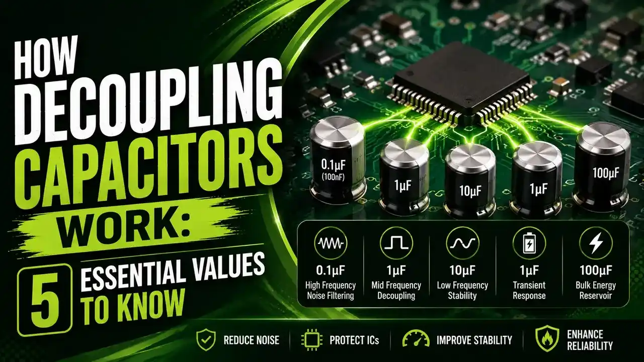
10 nF
Handles the fastest, highest frequency switching noise closest to the chip.
100 nF
The most common local decoupling value, a solid default starting point at almost every IC power pin.
1 uF
Supports slightly lower frequency events and adds extra local charge storage near groups of pins.
4.7 to 10 uF
Bulk decoupling positioned near clusters of chips rather than at a single pin.
47 uF and Above
Bulk energy storage near the voltage regulator, covering the slowest, largest current demands on the board.
Real designs place several of these values in parallel near each chip, so the combined set covers a much wider frequency range than any single value could alone.
Comparing Decoupling Capacitor Types
| Type | Typical Value | Distance from IC | Primary Role |
|---|---|---|---|
| Local Ceramic | 0.01 to 0.1 uF | Directly at the power pin | Fast, high frequency transient response |
| Mid Range Ceramic or Tantalum | 1 uF | Near a group of pins | Mid frequency support between local and bulk |
| Bulk Electrolytic | 10 to 100 uF | Near the chip cluster or regulator | Sustained current demand, lower frequency |
| Power Plane Capacitance | Not a discrete component | Distributed across the board | Very high frequency support beyond any discrete capacitor |
Why Poor Decoupling Causes Intermittent Faults
A circuit with weak decoupling often works fine on the bench and then fails intermittently once it is running a real workload, since the fault only appears during the fastest, most demanding switching events.
That voltage dip can flip a logic level at exactly the wrong instant, corrupt a data line, or bleed noise into a sensitive analog section sharing the same board.
Because the symptom looks random, teams often chase software or timing bugs for hours before realizing the real cause sits in the power delivery network, not the logic itself.
Decoupling Capacitor Do's and Don'ts
✓ Do
- Place the smallest value capacitor closest to the power pin, with larger values further out
- Use short, wide traces and a solid ground return path to keep loop inductance low
- Combine multiple values in parallel to cover a broad range of switching frequencies
- Add bulk capacitance near the voltage regulator to support sustained current draw
✗ Don't
- Rely on a single large capacitor to cover both fast and slow current demands
- Route the decoupling capacitor through a long or narrow trace to save board space
- Share a via between multiple capacitors when a dedicated via keeps inductance lower
- Ignore intermittent faults that only appear under real switching load
Guides on Power Integrity and Capacitor Placement
Decoupling Capacitor Questions Engineers Ask
External References
- Sierra Circuits: What Is the Use of a Decoupling Capacitor
- Best PCBs: Decoupling vs Bypass Capacitor, Differences and PCB Use
What We Learn Today
- A decoupling capacitor stores charge close to an IC and releases it instantly to cover fast current spikes the main power supply cannot follow.
- Placement close to the power pin matters as much as the value, since distance adds inductance that slows the response.
- Self resonant frequency sets the practical upper limit on the noise a given capacitor can filter.
- Real designs combine multiple capacitor values in parallel, local and bulk together, to cover a wide range of switching frequencies.