
Connect a thermocouple backwards, and it doesn't just fail. It reads a real, plausible-looking temperature that happens to be completely wrong.
Ok, let me explain it properly. Thermocouple polarity isn't marked with a plus and minus sign on the wire. You have to know how to read it, and there's more than one way to check.
Thermocouple polarity identification means correctly telling apart the positive and negative leads before connecting a thermocouple, since reversing them produces a stable but wrong reading, and it can be verified through standardized color codes, a simple magnet test on base metal types, or a heated-junction voltmeter check.
Thermocouple Polarity: How to identify?
Thermocouple polarity matters because a thermocouple only works correctly when its positive and negative legs are connected in the right order, all the way from the sensor to the instrument.
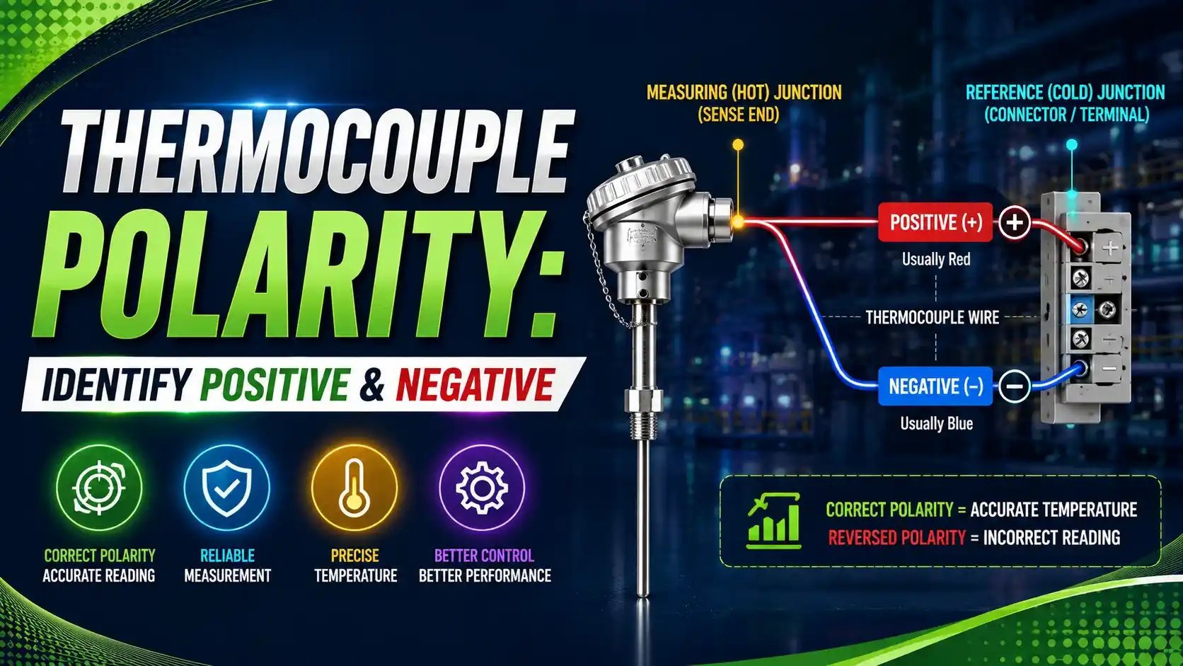
Have you got it so far? Good, because here's the part that catches people off guard. A reversed thermocouple doesn't fail obviously. It produces a real voltage, just with the wrong sign and the wrong slope.
At low temperature differences this can look almost plausible on a display, which is exactly why silent polarity mistakes are so dangerous. This ties closely into proper thermocouple installation practice.
Color Code Comparison: ANSI vs IEC
This is where a lot of confusion starts, because the two major standards don't agree with each other.
| Type | ANSI/ASTM Negative Lead | IEC 60584-3 Negative Lead | ANSI Positive Lead |
|---|---|---|---|
| K | Red | White | Yellow |
| J | Red | White | White |
| T | Red | White | Blue |
| E | Red | White | Purple |
| N | Red | White | Orange |
| R / S | Red | White | Black |
Notice the pattern. Under ANSI, the negative lead is always red, no matter the type. Under IEC, the negative lead is always white.
Only the positive lead's color changes by type under ANSI, and the overall jacket color changes by type under IEC. Mixing the two systems is one of the most common field mistakes, something also worth checking against our guide to thermocouple types and ranges.
Six Ways to Verify Thermocouple Polarity
Read the Color Code Correctly
Confirm which standard, ANSI or IEC, applies to the installed cable before trusting any wire color as an indicator.
Check the Connector Shape
Standard thermocouple plugs and jacks are keyed with one wide and one narrow pin, so they physically only fit one way when wired correctly.
Use a Small Magnet
On several base metal types, one leg is noticeably more magnetic than the other, offering a quick check when labels have faded or been removed.
Heat One Junction and Read the Sign
Gently warming one junction while reading a DC millivoltmeter reveals polarity directly, since the meter's sign tells you which lead is truly positive.
Compare Wire Appearance
Some alloy pairs have visibly different surface finishes, one duller or harder than the other, which experienced technicians learn to recognize by feel.
Check the Instrument's Reading Trend
If a known heat source causes the reading to fall instead of rise, that's a strong sign the polarity is reversed at some point in the loop.
The Magnet Test in Detail, and Why It Reverses Between Types
This is genuinely one of the more surprising facts in thermocouple work, so it's worth slowing down for.
For Type K, the negative leg, Alumel, contains nickel, aluminum, manganese, and silicon, which makes it weakly magnetic. The positive leg, Chromel, is a nickel-chromium alloy and is essentially non-magnetic.
For Type J, it flips. The positive leg is pure iron, strongly magnetic. The negative leg, Constantan, is a copper-nickel alloy and is non-magnetic.
Have you got it? Good, because this means the magnet test result means the opposite thing depending on thermocouple type. Always confirm the type first, or the magnet test can mislead you.
Try It: Polarity Verification Calculator
Gently heat one junction relative to a known cold reference, and this calculator estimates the expected EMF. A positive reading on your meter with the presumed positive lead on the red terminal confirms correct polarity.
Let Us Take an Example
A technician wants to confirm polarity on an unlabeled Type K thermocouple before installation.
They gently warm one junction to 80°C using a controlled heat source, while the reference junction stays at room temperature, 25°C.
Type K, S ≈ 41 µV/°C
Thot = 80°C
Tcold = 25°C
Step 1: Expected EMF in microvolts
E = S × (Thot − Tcold)
E = 41 × (80 − 25)
E = 41 × 55
E = 2255 µV
Step 2: Convert to millivolts
E = 2255 ÷ 1000
E = 2.255 mV
Have you got it? Good. With the presumed positive lead connected to the meter's positive terminal, a reading close to positive 2.255 mV confirms the polarity is correct.
Ok, let me explain what a wrong result looks like. If the meter instead shows roughly negative 2.255 mV, the leads are reversed, and swapping them fixes the issue immediately.
A Step-by-Step Polarity Verification Approach
Identify the thermocouple type
Confirm the exact type first, since color codes, magnet behavior, and expected EMF all depend on it.
Check the color code against the correct standard
Confirm whether the installation uses ANSI or IEC coding before trusting any wire color.
Try the magnet test if labels are unclear
Use a small magnet on base metal types, remembering the result means opposite things for Type K versus Type J.
Confirm with a heated-junction voltmeter check
Warm one junction gently and read the sign on a DC millivoltmeter for a definitive answer.
Verify polarity at every termination
Check polarity again at extension cable joints and instrument terminals, not just at the sensor.
Label the confirmed leads clearly
Mark verified leads permanently so future maintenance doesn't have to repeat the whole check.
Good Practices for Thermocouple Polarity
✓ Do
- Confirm which color code standard, ANSI or IEC, applies before trusting any wire color
- Use the magnet test only after confirming thermocouple type, since the result reverses by type
- Verify polarity with a heated-junction check whenever labels are missing or unclear
- Check polarity at every termination point along the full cable run
✗ Don't
- Assume red always means negative, since that's only true under the ANSI standard
- Trust a faded or damaged label without a physical or electrical verification check
- Rely on the magnet test result without first confirming the thermocouple type
- Skip re-checking polarity after any cable splice or termination change
Worth Reading if You Want to Go Deeper
Questions Students and Technicians Often Ask
External References
- How to Check Polarity of Thermocouples and Lead Wires, Hot Kilns
- Thermocouple Leads Polarity Identification, Instrumentation Tech
What we learn today
- Thermocouple polarity determines whether the sensor produces a correct reading, and reversing it creates a stable but wrong output rather than an obvious failure.
- ANSI marks the negative lead red for every type, while IEC marks it white for every type, making the two standards easy to confuse.
- The magnet test works oppositely for Type K and Type J, so thermocouple type must be confirmed before relying on it.
- A worked example showed a Type K junction heated to 80°C against a 25°C reference producing an expected 2.255 mV, confirming correct polarity when the sign matches.
- Polarity should be checked at every termination point along the cable run, not just at the sensor itself.