555 Timer IC Explained: Astable, Monostable, and Bistable Modes

Share:
Electronics & ICs

555 Timer IC Explained: Astable, Monostable, and Bistable Modes

Designed in 1971 with nothing but 25 transistors, 2 diodes, and 15 resistors, the 555 has outlived entire generations of newer chips because three resistors and a capacitor are still the fastest way to get a precise pulse or oscillation.

Electronics 555 Timer Oscillators 9 Min Read

The 555 timer is one of the most widely produced integrated circuits ever made, generating precise time delays and oscillations from just a handful of external resistors and capacitors. This guide covers its internal block diagram, all three operating modes, the timing formulas, and a live astable calculator.

What is a 555 Timer IC?

The 555 Timer is an 8-pin integrated circuit, originally designed by Hans Camenzind in 1971, that produces accurate time delays or oscillations using an external resistor-capacitor (RC) network. Despite its age, it remains one of the best-selling ICs in history, found in everything from toys and kitchen appliances to industrial timer circuits and even spacecraft.

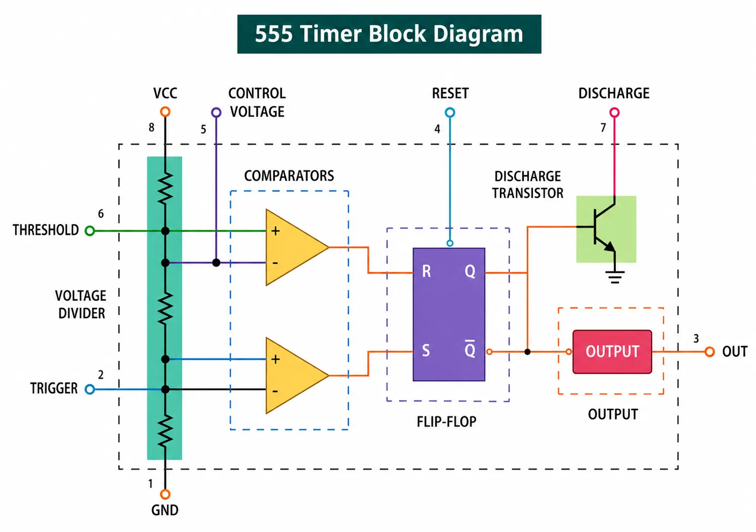
Internally, a standard 555 contains 25 transistors, 2 diodes, and roughly 15 resistors, arranged into two voltage comparators, a flip-flop, a discharge transistor, and an output stage. Three internal 5 kΩ resistors form a voltage divider that sets reference voltages at exactly 1/3 and 2/3 of the supply voltage, which is actually where the chip's name comes from.
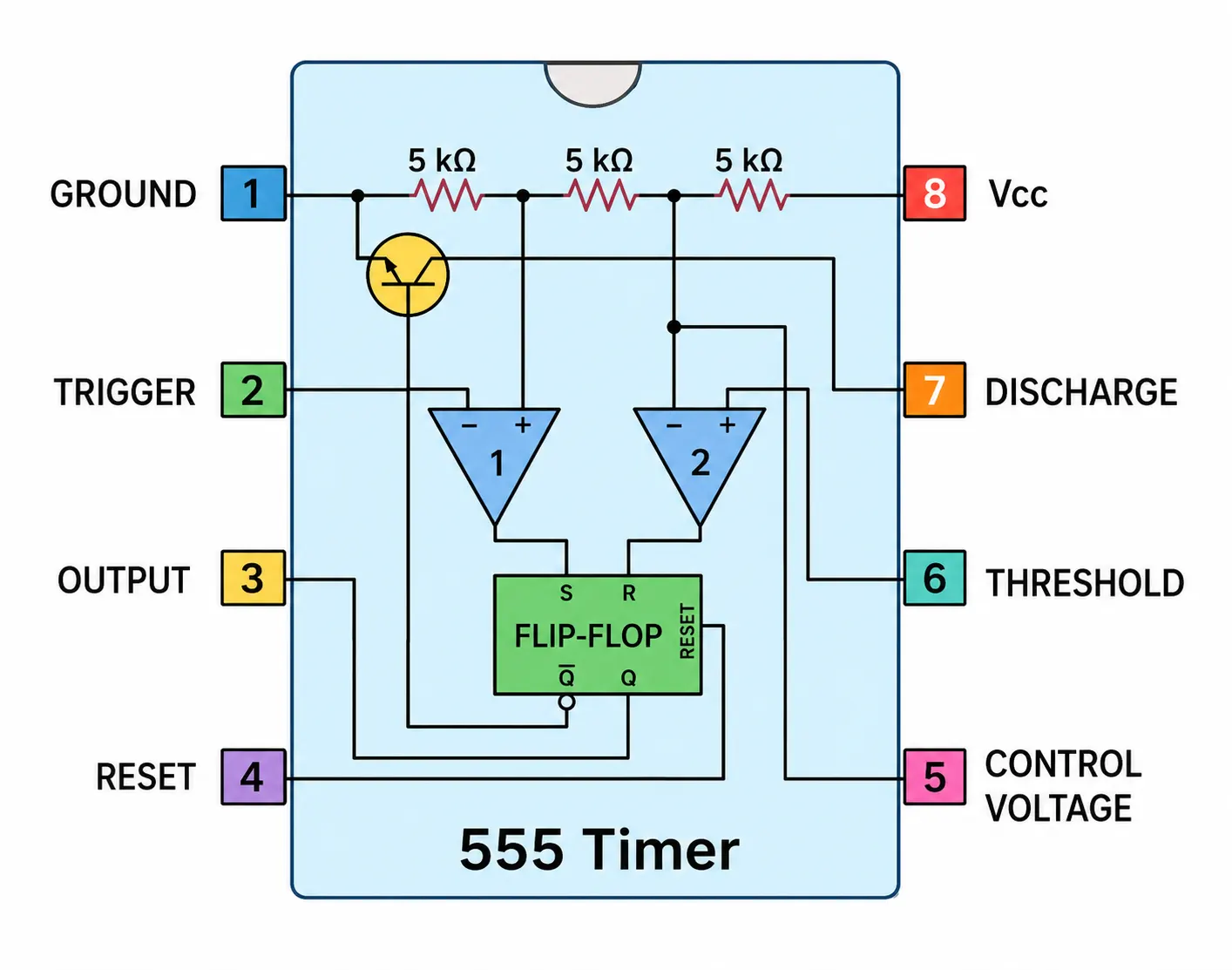
How-does-a-555-Timer-works
💡 Quick Summary: The 555 timer operates in three modes: astable (continuous oscillation, no stable state), monostable (a single timed pulse per trigger), and bistable (a simple flip-flop with two stable states). Astable and monostable are by far the most common in practice.

555 Timer Block Diagram?

555-Timer-block-diagram
Advertisement
Advertisement

Real Life Example

Think of the 555 astable mode as a light switch nobody is holding, one that keeps flipping itself on and off forever at a steady rate, like a blinking turn signal. The monostable mode is more like a bathroom exhaust fan with a timer switch: press it once, and it stays on for a fixed duration before turning itself back off, no matter how long you press the button.

📖 Did You Know? The "555" in the chip's name comes from the three internal 5 kΩ resistors that form the reference voltage divider inside the chip, not from any marketing decision.

The Three Operating Modes

🔄 Astable Mode

No stable state at all. The output continuously switches between High and Low, forming a free-running square wave oscillator.
Configuration: Two resistors (R1, R2) and one capacitor, with trigger and threshold pins tied together.
Best For: Clock pulses, LED flashers, tone generators, oscillators.

⏱️ Monostable Mode

One stable state. A single trigger pulse produces exactly one timed output pulse, then the chip returns to its stable state until triggered again.
Configuration: One resistor (R) and one capacitor (C), triggered by pulling the trigger pin low momentarily.
Best For: One-shot delays, debounce circuits, pulse-width generation.

🔀 Bistable Mode

Two stable states, functioning as a simple flip-flop. No timing capacitor is used; the output only changes when triggered or reset.
Configuration: No timing RC network, just trigger and reset inputs driving the internal flip-flop directly.
Best For: Simple latch or memory circuits, manual on/off switching.
Advertisement
Advertisement

555 Timer Formulas

Monostable Mode: Pulse Width
T = 1.1 × R × C
T = output pulse duration (seconds). R = timing resistor (ohms). C = timing capacitor (farads).

Astable Mode: Frequency and Duty Cycle
f = 1.44 / ((R1 + 2R2) × C)
Duty Cycle = (R1 + R2) / (R1 + 2R2) × 100%
The capacitor charges through both R1 and R2, but discharges only through R2, which is why the duty cycle can never go below 50% in the classic configuration.

Worked Example (Monostable)
R = 100 kΩ, C = 10 µF
T = 1.1 × 100,000 × 0.00001 = 1.1 seconds
💡 Engineering Tip: If R1 equals R2 in a standard astable circuit, the duty cycle works out to 2/3, or about 66%, not 50%, because the capacitor charges through both resistors but discharges through only one of them. A true 50% duty cycle needs a diode across R2 or a modified circuit.

555 Timer Astable Calculator

🧮

Astable Frequency and Duty Cycle Calculator

Classic two-resistor, one-capacitor astable configuration
-
Frequency (Hz)
-
Duty Cycle (%)
-
Period (ms)

Comparing the Three Modes

Mode
Stable States
Timing Components
Typical Use
Astable
0
R1, R2, C
Oscillator, clock pulses
Monostable
1
R, C
One-shot timer, debounce
Bistable
2
None
Latch, flip-flop

Applications of the 555 Timer

💡

LED and Lamp Flashers

Astable mode drives blinking indicators and warning lights at a set rate.

🔔

Tone Generators

Astable oscillation drives simple alarm and buzzer tone circuits.

⏲️

Delay Timers

Monostable mode provides fixed delay-on or delay-off timing for control circuits.

🔘

Switch Debouncing

Monostable pulses clean up noisy mechanical switch contacts before feeding logic circuits.

🕹️

Servo Motor Testing

Monostable pulse widths in the 1 to 2 ms range mimic standard servo control signals.

🔊

Frequency Division

Combined with counters, 555 astable output supports clock division circuits.

555 Timer IC: Video Walkthrough

Advertisement
Advertisement

Frequently Asked Questions About the 555 Timer

What is the difference between astable and monostable mode?
Astable mode has no stable state and continuously oscillates on its own. Monostable mode has one stable state and produces exactly one timed output pulse each time it receives a trigger.
Why can't a standard 555 astable circuit reach exactly 50% duty cycle?
Because the timing capacitor charges through both R1 and R2 but discharges only through R2, the high time is always longer than the low time in the classic configuration, keeping duty cycle above 50% unless a diode is added across R2.
What do the internal reference voltages of a 555 timer represent?
Three internal 5 kΩ resistors form a voltage divider, setting reference voltages at 1/3 and 2/3 of the supply voltage. These references, compared against the external RC network's voltage, are what actually give the "555" its name.
What is bistable mode used for?
Bistable mode uses the 555 as a simple flip-flop with two stable states and no timing capacitor, useful for basic latch circuits that need to hold a state until manually triggered or reset.
Is the 555 timer still relevant today with microcontrollers available?
Yes. For simple, low-cost timing or oscillation tasks, a 555 timer is often faster to design, cheaper, and more robust than adding a full microcontroller, which is why it remains widely used in hobbyist and industrial circuits alike.
External References
Advertisement
Advertisement

What We Learn Today

  • The 555 timer is a robust 8-pin IC that generates precise time delays or oscillations from a simple external RC network
  • Astable mode oscillates continuously with no stable state, monostable produces one timed pulse per trigger, bistable acts as a simple flip-flop
  • Monostable pulse width follows T = 1.1RC, while astable frequency follows f = 1.44/((R1+2R2)C)
  • A classic two-resistor astable circuit can never reach exactly 50% duty cycle without circuit modification
  • Despite decades of newer alternatives, the 555 remains a go-to choice for simple, low-cost timing applications
"I hope you like above blog. There is no cost associated in sharing the article in your social media. Thanks for Reading !! Happy Learning"

Leave a Reply

Your email address will not be published. Required fields are marked *