
A Wheatstone bridge turns a resistance change too small to measure directly into a clean, usable voltage signal. Here is exactly how the null balance principle works, the three ways the circuit gets wired, and 10 real places you will find it running today.
What Is a Wheatstone Bridge?
A Wheatstone bridge is an electrical measurement circuit that determines an unknown resistance by comparing it against known resistances arranged in a bridge configuration.
The circuit consists of two voltage divider paths, often called the legs of the bridge. When the resistance values are correctly balanced, the voltage difference between the two midpoints becomes zero.
No current flows through the measuring device at that point. This null-balance principle allows very small resistance changes to be detected with high accuracy.
That is exactly why Wheatstone bridges show up inside pressure sensors, strain gauges, load cells, and other precision instrumentation. If you work with resistance-based sensors regularly, our guides on RTD sensor connections and the RTD resistance to temperature calculator cover the same underlying resistance measurement principles from a different angle.

How a Wheatstone Bridge Measures Resistance
The circuit follows the same four-step sequence every time, whether it sits in a laboratory setup or inside a production pressure transmitter.
Known Resistors Set the Ratio
Two fixed, known resistors establish the reference ratio the unknown resistance will be compared against.
Excitation Voltage Energizes the Bridge
A stable DC voltage applied across opposite corners powers the whole circuit and makes imbalance measurable.
Bridge Reaches Balance or Imbalance
If the resistance ratios match, the bridge balances at zero output. If not, a voltage difference appears.
Output Voltage Reveals the Unknown
That voltage difference, however small, is measured and converted into the unknown resistance value.
Wheatstone Bridge Circuit Elements Explained
Six components work together to make this measurement possible. Here is what each one actually does.
Four Resistors Forming the Bridge
Connected in a closed loop forming a diamond-shaped network, split into two parallel legs.
Known Resistances, R1 and R2
Fixed reference values placed in two arms, usually precision-grade with low temperature drift.
Adjustable Resistance, R3
A variable resistor used to drive the bridge to balance, adjusted manually or electronically.
Unknown Resistance, R4 or Rg
Often a real sensor, such as a strain gauge or pressure element, whose resistance changes with input.
DC Excitation Voltage, VIN
A stable voltage source applied across opposite corners of the bridge to energize the circuit.
Measuring Instrument
A galvanometer or high-impedance voltmeter connected between the bridge midpoints to read imbalance.
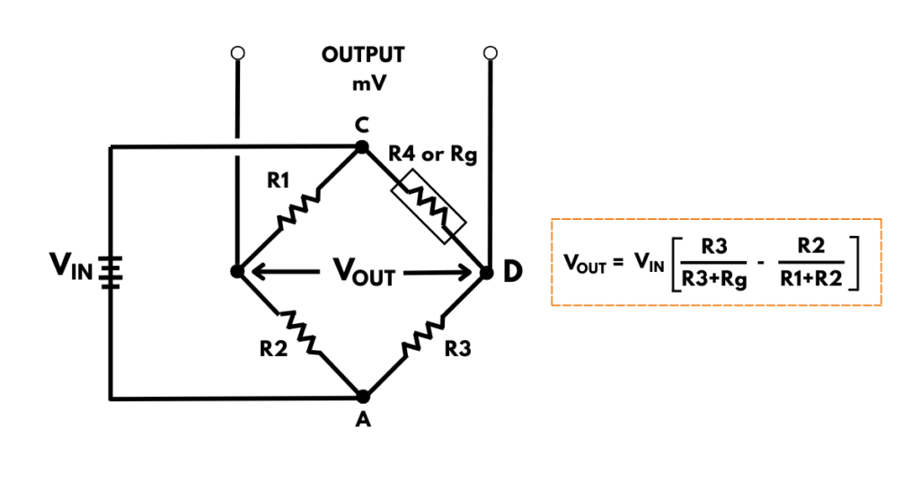
Balanced bridge, zero output: when the resistance ratio in one leg matches the ratio in the other, the voltage at both midpoints is equal, so no current flows through the measuring device. This zero-output condition lets the unknown resistance be calculated with simple ratios.
Unbalanced bridge, measurement mode: when the ratios no longer match, a small voltage difference appears between the midpoints and current flows through the measuring circuit. The size and direction of that voltage show how much the unknown resistance has changed.
Why it works this way: in real instrumentation systems, the bridge usually runs in unbalanced mode on purpose, so even tiny resistance changes caused by pressure, force, or temperature can be continuously measured rather than manually balanced each time.
Wheatstone Bridge Balance Formula
Written as an equation, the balance condition behind the whole circuit is straightforward.
Balance condition: R1 / R2 = R3 / Rx
Solved for the unknown: Rx = (R2 × R3) / R1
Worked example: R1 = 100 Ω, R2 = 100 Ω, R3 = 250 Ω
Rx = (100 × 250) / 100 = 250 Ω
Since R1 equals R2 in this example, the bridge balances exactly when Rx equals R3. That one-to-one relationship is precisely why R3 is called the adjustable arm, since dialing it in gives you the unknown resistance directly at the balance point.
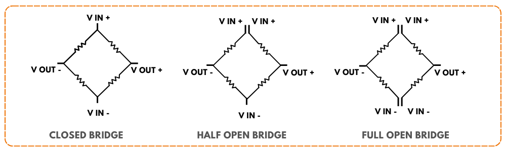
Bridge Configurations: Closed, Half-Open, and Full-Open
Depending on how the four resistors are interconnected, a Wheatstone bridge can be wired in three different ways, each with its own practical trade-offs.
Closed Bridge
All four resistors form one complete loop. Individual resistors cannot be measured separately, since each is electrically influenced by the other three. Common when the bridge acts as one complete sensor element.
Half-Open Bridge
Split into two branches connected at one end. Each resistor can now be measured individually, useful for evaluating sensor performance or drift, and supports compensation techniques with one extra connection.
Full-Open Bridge
Divided into two separate branches, open at both ends. Each half can be powered and measured independently, ideal for certain signal conditioners, though it needs more connections than a half-open bridge.
Why Strain Gauges Need a Wheatstone Bridge
A strain gauge produces a resistance change too small to measure accurately on its own. Placing it inside a Wheatstone bridge converts that tiny change into a proportional, measurable voltage. Click each tab to see how the three common strain gauge bridge types compare.
Only one arm of the bridge is an active strain gauge, with the remaining three as fixed resistors. Simple and low cost, but the least sensitive of the three options and offers no built-in temperature compensation.
Two arms carry active strain gauges, typically arranged so temperature effects on both gauges cancel out. Roughly double the sensitivity of a quarter bridge, with partial temperature compensation built in.
All four arms carry active strain gauges. This gives the highest sensitivity of the three configurations and the best temperature compensation, which is why it is standard in load cells and precision transducers.
Bridge Configuration Comparison Table
| Configuration | Individual Resistors Measurable | Compensation Support | Connections Needed |
|---|---|---|---|
| Closed Bridge | No | Limited | Fewest |
| Half-Open Bridge | Yes | Yes, one extra connection | Moderate |
| Full-Open Bridge | Yes | Yes, both active and passive | Most |
Most sensor manufacturers default to the closed configuration whenever the bridge is built as a single sealed element, since fewer connections mean fewer places for moisture or vibration to cause a fault. Half-open and full-open designs earn their extra wiring complexity mainly in lab and calibration settings, where being able to diagnose one arm at a time actually matters.
10 Surprising Applications of a Wheatstone Bridge
This bridge circuit converts tiny resistance changes into measurable electrical signals, which is exactly why it turns up in far more places than most people expect.
Resistance Measurement
The original use case, accurately determining an unknown resistance by balancing against known resistors.
Strain Measurement
Detects the minute resistance change in strain gauges, used in load cells and structural monitoring.
Temperature Measurement
Converts small resistance shifts in thermistors and RTDs into a measurable voltage signal.
Pressure Measurement
Most pressure transmitters use a bridge internally, converting diaphragm strain into an electrical output.
Level Measurement
Certain level techniques use mechanical movement or sensor deformation translated through a bridge circuit.
Gas Detection Sensors
Some gas sensors change resistance on exposure to specific gases, detected accurately by the bridge.
Medical Instrumentation
ECG and EEG systems apply the same bridge concepts to detect very small bio-electrical variations.
Industrial Automation Systems
Transmitters and sensors use bridges internally to monitor pressure, temperature, force, and strain reliably.
Robotics and Mechatronics
Bridge-based sensors measure force, torque, and position so robots respond accurately to contact.
Automotive Sensors
Pressure, load, and temperature sensors rely on bridge circuits for reliable readings under harsh conditions.
Notice how many of these ten applications have nothing to do with electronics on the surface. A load cell in a truck scale, an EEG electrode on a patient's scalp, and a MEMS pressure sensor inside a car's tire monitor all lean on the exact same null-balance idea underneath. That reuse across such different fields is a big part of why this circuit, first described in the 1840s, still shows up in brand new sensor designs today.
Advantages and Limitations of This Bridge Circuit
Why the Bridge Excels at Precision
Practical Limitations to Know
Try It: Wheatstone Bridge Balance Calculator
Enter three known resistor values and the actual unknown resistance to see whether the bridge is balanced, and by how much.
Download Bridge Circuit References
These two resources go deeper into official signal conditioning and strain gauge bridge theory.
Signal Conditioning Wheatstone Resistive Bridge Sensors
Official Texas Instruments application note on bridge sensor signal conditioning
Applying the Wheatstone Bridge Circuit
Classic HBM technical guide by Karl Hoffmann on strain gauge bridge theory
Watch: Wheatstone Bridge With Strain Gauge Explained
This video walks through building and reading a Wheatstone bridge circuit with a real strain gauge.
FAQs on Wheatstone Bridge Circuits
External References
- Texas Instruments, Signal Conditioning Wheatstone Resistive Bridge Sensors
- HBM, Applying the Wheatstone Bridge Circuit by Karl Hoffmann
- DwyerOmega, What Is a Wheatstone Bridge?
- DwyerOmega, What Are Strain Gauges?
- YouTube, Wheatstone Bridge with Strain Gauge Explained
What we learn today
- A Wheatstone bridge measures unknown resistance by balancing it against known resistors using the null-balance principle.
- The balance condition follows one simple ratio, R1/R2 equals R3/Rx, which can be rearranged to solve directly for the unknown.
- Closed, half-open, and full-open bridge configurations trade off diagnostic access against wiring complexity.
- Quarter, half, and full bridge strain gauge setups trade sensitivity and temperature compensation for simplicity.
- The same core circuit shows up in pressure transmitters, load cells, medical devices, robotics, and automotive sensors alike.