
Table of Contents
ToggleWhat Is Sensor Linearity and What Does It Mean?
In instrumentation and measurement systems, sensors are expected to convert a physical quantity into an electrical signal as accurately and predictably as possible.
Whether the sensor is measuring pressure, temperature, flow, level or displacement, engineers rely on the sensor output to represent the actual process condition. One of the most important parameters that defines this behavior is Sensor Linearity.
Sensor-Linearity is often mentioned in datasheets, but it is also one of the least understood specifications. Many engineers look only at accuracy or range and overlook how linear the sensor response really is.
This article explains Sensor-Linearity and shows why it directly affects calibration, scaling, and measurement uncertainty.
Understanding Sensor Linearity
Sensor-Linearity describes how closely a sensor’s output follows a straight-line relationship with its input over the entire measurement range.
In an ideal sensor:
A proportional increase in input produces a proportional increase in output
The input–output relationship forms a perfect straight line
Calibration becomes simple and predictable
In real sensors, this ideal condition never exists. Small deviations always occur, and these deviations are described as Sensor Linearity error or non-linearity.

What Is Sensor Linearity Error or Non-Linearity?
Sensor-Linearity error is defined as the maximum deviation of the actual sensor output from a reference straight line, measured under constant environmental conditions.
This deviation is not noise or random fluctuation. It is a systematic difference between the expected output and the actual output of the sensor.
To understand this clearly:
Known input values are applied across the full sensor range
The corresponding output values are recorded
A straight reference line is selected
The largest deviation from this line is taken as the Sensor Linearity error
The smaller this deviation, the better the Sensor Linearity.
Why the Reference Straight Line Is Important
Sensor-Linearity cannot be defined without first defining the reference straight line. Different reference lines can produce different linearity values for the same sensor.
Common reference lines include:
End-point straight line
Zero-based straight line
Best Fit Straight Line (BFSL)
Among these, the Best Fit Straight Line is the most widely accepted and practically meaningful method.
Best Fit Straight Line and Sensor Linearity
The Best Fit Straight Line is calculated using the least squares method, which minimizes the total squared deviation between all measured data points and the straight line.
This method is preferred because:
It represents the overall sensor behavior, not just the endpoints
Positive and negative deviations are balanced
It reflects real-world performance during normal operation
Most reputable sensor manufacturers specify Sensor-Linearity error with respect to the Best Fit Straight Line because it provides a realistic and statistically sound representation of sensor performance.
Why Sensor Linearity Matters in Calibration
Sensor-Linearity is very important during calibration and scaling.
When Sensor Linearity is good:
A simple linear scaling equation is sufficient
Fewer calibration points are required
Measurement uncertainty is reduced
When Sensor Linearity is poor:
Multi-point calibration becomes necessary
Software linearization may be required
Errors increase at mid-range values
In control systems, poor Sensor-Linearity can lead to incorrect control action even if the sensor appears accurate at the calibration points.
Interaction of Sensor Linearity with Other Errors
Sensor-Linearity does not exist in isolation. Several other error sources influence the final measurement result.
To correctly interpret a Sensor Linearity specification, the following conditions must be satisfied:
Stable environmental conditions
Temperature, humidity, and vibration must be controlled. Thermal drift can easily mask linearity effects.Good repeatability
The sensor must give the same output for the same input every time. Poor repeatability makes Sensor Linearity meaningless.Low hysteresis
The output should not depend on whether the input is increasing or decreasing. Hysteresis often appears as false non-linearity.Linear signal conditioning electronics
Amplifiers, ADCs, and transmitters must have negligible non-linearity compared to the sensor.Adequate resolution
The sensor and readout resolution must be fine enough to detect small deviations caused by Sensor Linearity error.
Why Sensor Errors Cannot Be Added Directly
Measurement errors are often misunderstood. Sensor-Linearity error cannot simply be added to other errors.
Instead, uncertainties are combined using the Root-Sum-Squares (RSS) method.
This means:
Each error contributes based on its magnitude
Large errors dominate the total uncertainty
Improving Sensor Linearity alone may not improve accuracy if other errors are larger
This is why system-level accuracy analysis is essential, not just sensor-level specifications.
How Sensor Linearity Is Specified
Sensor-Linearity is usually expressed as a percentage of output span.
For unipolar sensors:
Linearity is specified as ± % of Full Scale Output (FSO)
For bipolar sensors:
Linearity is specified as ± % of Full Range Output (FRO)
This includes both positive and negative output ranges
Understanding this distinction is important when comparing different sensor datasheets.
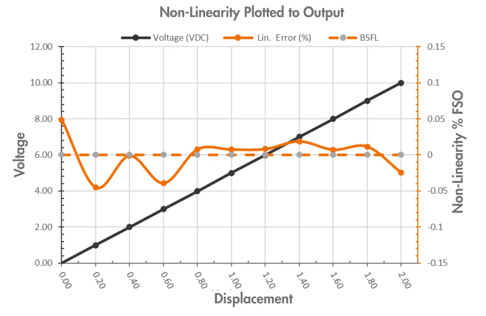
Practical Example of Sensor Linearity
Consider a displacement sensor with:
Measurement range: 0 to 2 inches
Output signal: 0 to 10 V DC
Sensor Linearity error: ±0.25 % of FSO
Now analyze the effect:
Full Scale Output = 10 V
Linearity error = ±25 mV
Scale factor = 5 V per inch
Equivalent displacement error = ±0.005 inches
This example shows how Sensor Linearity directly translates into real measurement error that must be evaluated against application requirements.
What we learn today?
Sensor Linearity is not just a datasheet number but it directly influences how reliable and predictable a measurement system will be in real operation.
A sensor with good Sensor Linearity makes calibration easier, reduces scaling errors, and improves confidence in the measured values across the entire range.
At the same time, Sensor Linearity must always be viewed along with other error sources such as temperature effects, repeatability, hysteresis, and resolution, since measurement uncertainty is the combined result of all these factors.
By understanding Sensor Linearity properly and evaluating it in the context of the complete measurement system, engineers can select the right sensor, design better calibration strategies, and achieve more accurate and stable process measurements over the long term.


I hope you like above blog. There is no cost associated in sharing the article in your social media. Thanks for Reading !! Happy Learning