Table of Contents
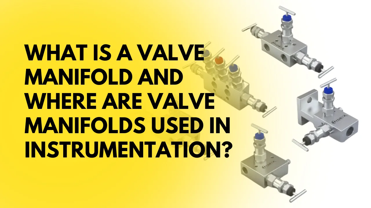
ToggleValve Manifold: Introduction
In many industrial plants, several valves are often required to control, isolate, or balance the flow of fluids in a system. Installing each valve separately can make the piping arrangement complicated and difficult to maintain. This is where valve manifolds become very useful.
A valve-manifold is a compact device that combines multiple valves into a single unit. Instead of installing separate valves and fittings, the manifold allows operators to manage fluid flow, isolate instruments, and perform maintenance using one integrated assembly.
Valve manifolds are widely used in process industries such as oil and gas, power plants, chemical plants, water treatment facilities, and manufacturing systems. They are especially common in instrumentation applications where pressure transmitters, differential pressure transmitters, and pressure gauges need reliable isolation and control.
Even with the continuous development of new instrumentation technologies, valve manifolds remain a trusted and practical solution for fluid control when two or more valves are required in a system.
In this article, we will explore the following questions:
What is a valve manifold?
Why are valve manifolds used in instrumentation systems?
What types of valve manifolds are available?
Where are valve manifolds commonly used in industrial applications?
Understanding valve-manifolds helps technicians, engineers, and maintenance teams operate instrumentation systems more safely and efficiently.
What is a Valve Manifold? How Does It Work?
In many industrial processes, instruments such as pressure transmitters, differential pressure transmitters, and pressure gauges need multiple valves installed very close to each other. These valves perform different functions such as isolation, venting, draining, or equalizing pressure.
When a system requires several valves in the same location, engineers must decide how those valves will be installed.
1. Using Individual Valves
One possible solution is to install separate individual valves connected through fittings and tubing. While this approach can work, it has several disadvantages.
First, the installation becomes complex and bulky. Multiple valves, connectors, and fittings require more piping space and make the overall assembly larger.
Second, this method can be more expensive to install and maintain. Each valve must be installed, connected, and tested individually.
Third, using many fittings increases the number of possible leak points in the system. In process industries where safety and reliability are critical, additional leak paths are always a concern.
Because of these limitations, this approach is rarely preferred in modern instrumentation systems.
2. Using a Valve Manifold
A much better and more practical solution is the use of a valve manifold.
A valve manifold is a compact device that integrates multiple valves into a single block assembly. Instead of installing separate valves, the manifold combines them into one unit that connects the process line to the measuring instrument.
In simple terms, a valve manifold acts as a bridge between the process and the instrument. Inside the manifold block, the valves are arranged in a predefined configuration designed by engineers to perform specific functions.
How a Valve Manifold Works?
The main purpose of a valve manifold is to control and manage the flow or pressure between the process and the instrument. Depending on the configuration, the valves inside the manifold can perform several tasks.
Isolation:
Isolation valves allow the instrument to be separated from the process line. This is important during maintenance or troubleshooting.
Equalization:
In differential pressure measurement systems, equalizing valves balance the pressure between the high-pressure and low-pressure sides.
Venting or Draining:
Some manifolds include vent or drain valves that allow operators to safely release trapped pressure or fluid.
Calibration and Maintenance:
A major advantage of valve manifolds is that they allow technicians to calibrate, test, or replace instruments without shutting down the entire process system.
Why Valve Manifolds Are Preferred
Valve manifolds are widely preferred in instrumentation because they offer several advantages compared to individual valve installations.
They provide a compact and space-saving design, reduce the number of fittings, and minimize potential leakage points. Installation is also faster, and maintenance becomes easier for technicians.
Because of these benefits, valve manifolds have become a standard solution in modern industrial instrumentation systems, especially for pressure and differential pressure measurement applications.
What Process Variables Are Measured Using Valve Manifolds?
Valve manifolds are commonly used in instrumentation systems where important process variables need to be measured accurately and safely. In most industrial applications, manifolds are connected to measuring instruments that monitor key operating conditions of the process.
The four main process variables associated with valve manifold applications are the following.
1. Pressure (Gauge and Differential)
Pressure is the most commonly measured variable when valve manifolds are used. Manifolds are typically installed with pressure transmitters, differential pressure transmitters, or pressure gauges.
Two types of pressure measurements are commonly involved.
Gauge Pressure
Gauge pressure refers to the pressure measured relative to atmospheric pressure. In this case, the reference point is the surrounding air pressure. When a gauge shows zero, it means the system pressure is equal to atmospheric pressure.
Gauge pressure is widely used in industrial systems such as compressed air lines, water pipelines, steam systems, and hydraulic circuits.
Differential Pressure
Differential pressure (DP) is the difference between two pressure points in a system. Differential pressure transmitters use two pressure inputs high pressure and low pressure to calculate this difference.
DP measurement is very important in instrumentation because it is also used to determine other process variables such as:
Flow rate
Liquid level in tanks
Density of fluids
Viscosity of liquids and gases
In many cases, sudden changes or fluctuations in differential pressure may indicate blockages, leaks, or other issues in the process line.
2. Flow Rate
Valve manifolds are frequently used with differential pressure flow measurement systems, such as orifice plates, venturi tubes, and flow nozzles. In these systems, the pressure difference created by the restriction is measured and used to calculate the flow rate.
3. Fluid Level
In tank level measurement, differential pressure transmitters are often installed with 3-valve or 5-valve manifolds. The pressure difference between the top and bottom of the tank helps determine the liquid level.
4. Temperature
Although valve manifolds are primarily associated with pressure measurements, they may also be used in systems where temperature instruments require isolation or safe maintenance. In such cases, manifolds help isolate the instrument during calibration or replacement.
Because of their flexibility and safety benefits, valve manifolds play an important role in accurate measurement and control of key process variables in industrial plants.
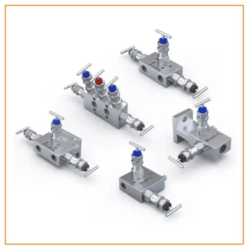
What Are the Different Configurations of Valve Manifolds?
Valve manifolds are available in several configurations depending on the instrumentation requirement and the function they need to perform. Although their designs may vary, all manifolds follow the same basic principle combining multiple valves into a single compact body.
A valve manifold block usually contains several internal passages and ports. These ports allow connections between the process line, the measuring instrument, and sometimes calibration equipment. By opening or closing the valves in the manifold, operators can isolate, equalize, vent, or drain the system safely.
The number and type of valves installed inside the manifold depend on the purpose of the application. For example, some applications only require isolation valves, while others require equalizing or vent valves as well.
In industrial instrumentation, valve manifolds are generally classified into three main configurations:
2-Valve Manifold
3-Valve Manifold
5-Valve Manifold
Each configuration is designed for specific measurement applications, particularly in pressure and differential pressure measurement systems.
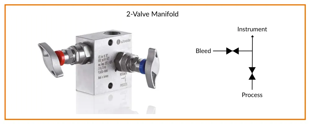
2-Valve Manifold
A 2-valve manifold consists of one block valve and one bleed (or test) valve. It performs the same function as a block-and-bleed valve arrangement.
The block valve isolates the instrument from the process line, while the bleed valve is used to release pressure or connect a calibration device.
During normal operation, the bleed valve remains closed and the block valve stays open. For calibration or maintenance, the block valve is closed and the bleed valve is opened to vent the pressure or connect a pressure calibrator.
This type of manifold is commonly used with pressure gauges, pressure transmitters, and pressure switches. However, it is not suitable for differential pressure transmitters because it has only one process connection.
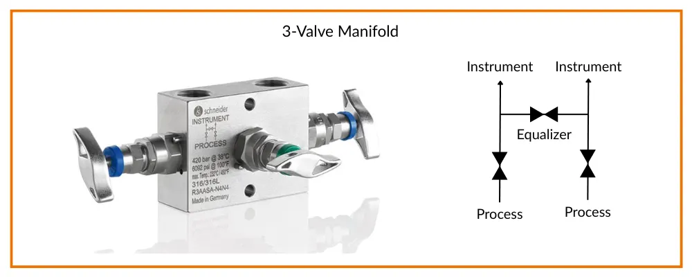
3-Valve Manifold
A 3-valve manifold contains two block valves and one equalizing valve. It is mainly used with differential pressure (DP) transmitters.
The two block valves connect the transmitter to the high-pressure and low-pressure sides of the process, while the equalizing valve balances the pressure between both sides.
During normal operation, the block valves remain open and the equalizing valve stays closed. When calibration or zero checking is required, the block valves are closed and the equalizing valve is opened to equalize pressure across the transmitter.
A 3-valve manifold helps protect the transmitter from over-range pressure and allows safe maintenance. However, it usually does not include test or vent connections, which limits its use in some industries.
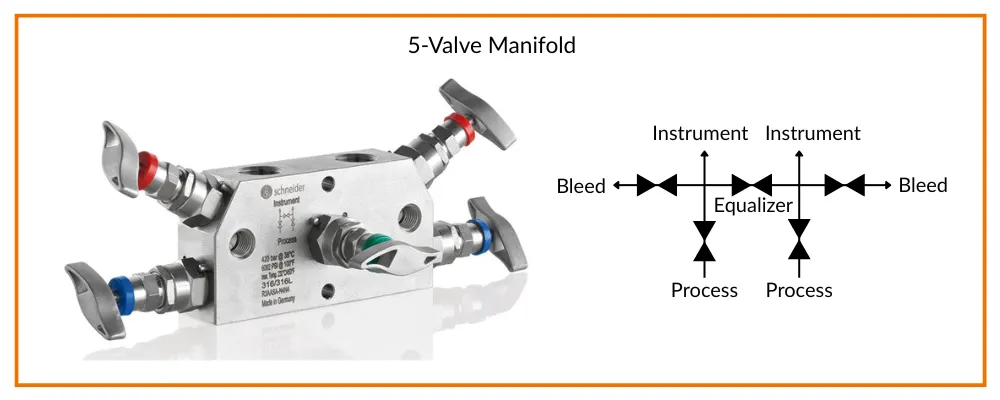
5-Valve Manifold
The 5-valve manifold is the most commonly used configuration for differential pressure transmitters.
It includes two block valves, one equalizing valve, and two additional valves for venting or testing. This design allows operators to isolate, equalize, vent, and calibrate the instrument easily.
During normal operation, the block valves are open while the equalizing and vent valves remain closed. For calibration, the block valves are closed and the equalizing valve is opened to check the transmitter’s zero.
The additional vent or test valves allow pressure release and calibration without removing the transmitter from the system, making the 5-valve manifold very practical for industrial applications.
One important rule is that the equalizing valve should never be opened while both block valves are open, as this could allow process fluid to flow from the high-pressure side to the low-pressure side.
Body Styles of Valve Manifolds
Valve manifolds are generally available in two main body styles: horizontal and vertical. The difference between them is mainly the orientation of the manifold body and valve arrangement.
The selection of the body style usually depends on the available installation space and the piping layout of the process system.
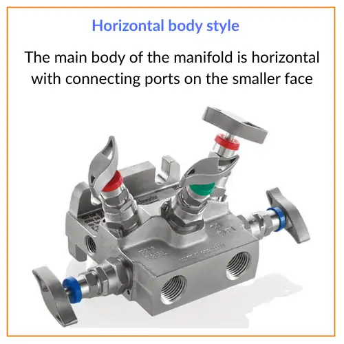
1. Horizontal Body Style
In a horizontal body style manifold, the valves are arranged horizontally. This design is commonly used where side mounting or horizontal piping connections are required.
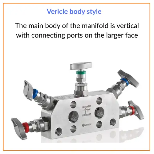
2. Vertical Body Style
In a vertical body style manifold, the valves are arranged vertically. This style is often preferred where space is limited or vertical mounting with transmitters is more convenient.
Mounting Styles of Valve Manifolds
Valve manifolds can be installed using two common mounting styles: direct mounting and remote mounting. The choice depends on the instrument location, process conditions, and installation requirements.
1. Direct Mounting
In direct mounting, the manifold is connected directly to the pressure instrument, such as a pressure or differential pressure transmitter. This connection is usually done using flange or threaded connections.
Direct mounting offers several advantages:
Lower installation cost
Fewer leak points
Simpler maintenance
Reduced pressure drop and heat loss
Because the instrument and manifold are connected together, the system becomes more compact and efficient.
2. Remote Mounting
In remote mounting, the manifold is installed away from the measuring instrument and connected using tubing and threaded fittings.
This method is useful when the process temperature or environment could damage or affect the instrument. By placing the manifold away from the instrument, the system provides better protection and easier installation.
What we learn today?
Valve manifolds are compact devices that combine multiple valves into a single unit to improve control, safety, and reliability in instrumentation systems. They allow operators to isolate, vent, equalize, or test instruments without shutting down the entire process.
Valve manifolds also play an important role in measuring key process variables such as pressure, differential pressure, flow rate, level, and temperature. By reducing the number of fittings and connections, they help minimize leakage points and simplify installation and maintenance.
Because of these advantages, valve manifolds are widely used in industrial plants and are available in different configurations to suit various measurement applications.


I hope you like above blog. There is no cost associated in sharing the article in your social media. Thanks for Reading !! Happy Learning