Vortex Shedding Flowmeter Flow Measurement

Vortex Shedding Flowmeter – Working Principle, Advantages, Limitations & Installation Guide

Share:

Vortex Shreding Flowmeter: Introduction

When it comes to reliable and maintenance-free flow measurement in steam, gas, and liquid applications, the Vortex Shedding Flowmeter stands out as one of the most trusted technologies in the instrumentation industry.

Unlike mechanical meters, a Vortex Shedding Flowmeter has no moving parts. Instead, it uses fluid dynamics principles to measure flow accurately.

But how does it really work?

Why is it widely used in steam systems?

And what are its practical limitations?

Let’s understand everything.

What is a Vortex Shedding Flowmeter?

A Vortex Shedding Flowmeter is a velocity-type flowmeter that measures flow based on the formation of vortices when fluid passes a bluff body inside a pipe.

When a non-streamlined object (called a bluff body) is placed in a flowing fluid, alternating vortices are created behind it. 

These vortices are known as the Kármán vortex street.

The frequency of vortex formation is directly proportional to the fluid velocity. By detecting and counting these vortices, the Vortex Shedding Flowmeter calculates the flow rate.

This principle works for:

  1. Steam

  2. Gases

  3. Clean liquids

Vortex Shedding Flowmeter Working Principle

Working Principle of Vortex Shedding Flowmeter

Now let’s understand the working principle in detail.

1. Presence of a Bluff Body

Inside the Vortex Shedding Flowmeter, a bluff body is installed in the center of the pipe.

This bluff body partially blocks the flow and forces the fluid to move around it.

2. Fluid Acceleration and Pressure Change

When fluid approaches the bluff body:

  1. Fluid near the surface slows down due to friction.

  2. Fluid in the reduced area between the body and pipe wall accelerates.

  3. This creates a pressure difference on alternate sides.

On the high velocity side → Pressure becomes low.
On the low velocity side → Pressure becomes high.

3. Formation of Vortices

After the fluid passes the bluff body, it tries to fill the empty region behind it.

This causes rotational motion and forms spinning vortices.

These vortices:

  1. Are shed alternately from each side

  2. Create a repeating pattern

  3. Have a frequency proportional to velocity

4. Detection of Vortex Frequency

Sensors detect the pressure pulses created by vortex shedding.

The frequency of vortex shedding (f) is related to velocity (V) by the Strouhal relationship:

f ∝ V

Because velocity is proportional to flow rate, the Vortex Shedding Flowmeter can accurately calculate flow.

The frequency of shedding is proportional to the Strouhal number (Sr), the flow velocity, and the inverse of the bluff body diameter.

The Strouhal number is determined experimentally and stays nearly constant over a wide range of Reynolds numbers. This means the vortex shedding frequency is independent of fluid density and directly proportional to fluid velocity for a given bluff body diameter.

For example:

k = A constant for all fluids on a given design of flowmeter

The volume flowrate qv in a pipeline can be calculated as

Vortex Flow Meter Formula

Key Components of a Vortex Shedding Flowmeter

A typical Vortex Shedding Flowmeter consists of:

  1. Bluff Body – Generates vortices

  2. Sensor – Detects pressure or vibration pulses

  3. Transmitter – Converts frequency to flow signal (4-20 mA)

  4. Flow Tube – Housing for the internal components

No moving parts means low maintenance and long life.

Why is Vortex Shedding Flowmeter Popular for Steam?

Steam measurement is challenging due to:

  1. High temperature

  2. High pressure

  3. Variable density

The Vortex Shedding Flowmeter is ideal because:

  1. It can handle high temperatures.

  2. It does not rely on mechanical movement.

  3. It provides stable measurement over a wide range.

However, steam quality and installation must be correct.

Advantages of Vortex Shedding Flowmeter

Let’s look at the major advantages.

1. No Moving Parts

This is the biggest benefit.

No wear and tear means:

  1. Low maintenance

  2. Long operational life

  3. High reliability

2. Reasonable Turndown Ratio

The Vortex Shedding Flowmeter offers good turndown, provided high velocities and pressure drops are acceptable.

3. Suitable for Liquids, Gases and Steam

One meter type can be used across multiple applications.

4. Little Resistance to Flow

Compared to differential pressure flowmeters, the pressure loss is relatively moderate.

5. Stable Over Time

Because it is frequency-based measurement, accuracy remains stable.

Disadvantages of Vortex Shedding Flowmeter

Every technology has limitations. The Vortex Shedding Flowmeter is no exception.

1. Poor Performance at Low Flow

At very low velocities:

  1. Vortices are not formed properly.

  2. Pulses are weak or absent.

  3. Meter may read low or even zero.

This makes the Vortex Shedding Flowmeter unsuitable for very low flow conditions.

2. High Maximum Velocity Claims

Manufacturers often quote maximum velocities of 80–100 m/s.

In real steam systems:

  1. Wet steam

  2. Dirty steam

  3. Erosion risk

These high velocities can create serious operational issues.

Lower practical velocities reduce the effective measuring capacity of the Vortex Shedding Flowmeter.

3. Sensitivity to Vibration

External pipeline vibration can interfere with vortex detection.

This may cause measurement errors.

4. Installation Sensitivity

Correct installation is critical.

Problems can occur if:

  1. Gaskets protrude into the pipe.

  2. Weld beads are not properly ground.

  3. Flow profile is disturbed.

These issues create unwanted vortices and reduce accuracy.

5. Long Straight Pipe Requirement

Just like an orifice plate, the Vortex Shedding Flowmeter requires:

  1. Long upstream straight length

  2. Adequate downstream straight length

Poor piping design directly affects performance.

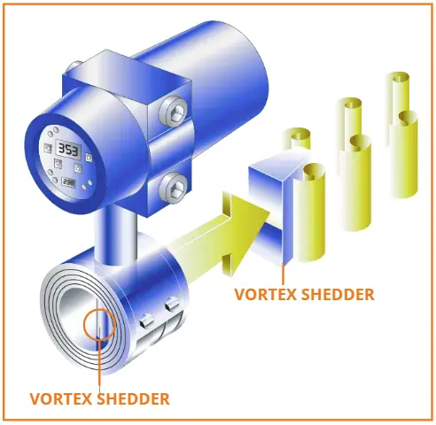
Typical Installation of Vortex Shreding Flowmeter

Installation Best Practices

Proper installation ensures accurate results.

1. Provide Straight Pipe Length

Typically:

  1. 10–20D upstream

  2. 5D downstream

(Check manufacturer recommendations.)

2. Avoid Vibration

Install supports near the meter.

Avoid mounting near pumps or compressors.

3. Ensure Clean Internal Surface

Remove weld slag, burrs, and protruding gaskets.

4. Install in Full Pipe Condition

For liquid applications, ensure the pipe is always full.

I hope you like above blog. There is no cost associated in sharing the article in your social media. Thanks for Reading !! Happy Learning

Leave a Reply

Your email address will not be published. Required fields are marked *