Table of Contents
ToggleOrifice Plate Sizing: Introduction
Orifice plates are thin metal plates with a precisely machined hole at the center. They are installed inside a pipeline to create a restriction in the flowing fluid. When the fluid passes through this restriction, a pressure drop is generated across the plate.
By measuring this pressure difference, we can calculate the flow rate using differential pressure principles.
Orifice plate sizing is important in flow measurement. A wrong size can lead to inaccurate readings, excessive pressure loss, or unstable process conditions. The bore diameter, pipe size, fluid properties, and required flow range all influence the final selection.
In this article, we will clearly understand what orifice plate sizing means, how it is determined, and why proper sizing is critical for accurate industrial flow measurement.
Orifice Plate Sizes
An orifice plate is a thin, flat metal plate with a precisely machined hole at its center. The upstream edge of this hole is sharp and square, which is very important for accurate flow measurement. When installed inside a pipeline, the plate creates a restriction that produces a pressure drop. By measuring this pressure difference, the flow rate can be calculated.
Orifice plates are widely used in industries such as oil and gas, chemical processing, water and wastewater treatment, power plants, and HVAC systems. Their simple design, reliability, and cost-effectiveness make them one of the most common primary flow elements in differential pressure measurement.
Depending on the process requirement and fluid characteristics, orifice plates are manufactured in different bore configurations.
1. Concentric Bore Orifice Plate
This is the most commonly used type. The hole is located exactly at the center of the plate.
Concentric orifice plates are mainly used for clean liquids, gases, and steam applications. They are preferred because they are economical, easy to manufacture, and supported by well-established flow coefficients under standards such as ISO 5167.
Due to their accuracy and predictable performance, concentric plates are considered the industry standard for general-purpose flow measurement.
2. Eccentric Bore Orifice Plate
In this type, the bore is offset from the center and positioned near the pipe wall.
Eccentric orifice plates are suitable for fluids that contain small amounts of gas bubbles in liquids or minor solid impurities. The offset hole allows entrained air or particles to pass without accumulating at the upstream side of the plate.
3. Segmental Bore Orifice Plate
The segmental type has a bore shaped like a half-circle segment.
It is commonly used for fluids containing heavy sediments, slurries, or solid particles. The open segment helps prevent clogging and allows solids to move freely through the pipe.
4. Quadrant Edge Orifice Plate
This type has a rounded (quadrant) inlet edge instead of a sharp edge.
Quadrant edge plates are suitable for fluids with high viscosity or for applications operating at low Reynolds numbers. The rounded edge improves measurement stability under such flow conditions.
This article focuses specifically on the concentric bore type orifice plate, as it is the most widely adopted standard design for general industrial applications. In the next sections, we will explore standard orifice plate sizes, bore diameter selection, and the key factors that influence proper sizing for accurate flow measurement.
Orifice Plate Sizing:
In addition to different bore configurations, orifice plates are manufactured in a wide range of sizes to suit various flow rates, operating pressures, and pipe diameters.
Typically, they are available for line sizes starting from ½ inch and extending up to 36 inches, covering most standard industrial applications.
When manufacturers specify orifice plate sizes, they usually provide detailed dimensional information. This includes the overall plate diameter, handle dimensions (such as height and width), plate thickness, and the bore diameter. These dimensions are not the same for all applications.
They vary depending on the nominal pipe size and the pressure rating of the flange system, as shown in the reference table below.
The correct orifice plate size and dimensions for any application are not selected randomly. They are determined based on well-established industry standards to ensure accuracy, safety, and consistency.
For example, the American Petroleum Institute provides sizing and installation recommendations in API RP 550, which is widely followed in petroleum, chemical, and refinery installations.
In addition, the International Organization for Standardization and the American Society of Mechanical Engineers have published internationally recognized standards for differential pressure flow measurement. These include ISO 5167 and ASME MFC-3M, which cover the use of orifice plates, flow nozzles, and Venturi tubes in circular pipes.
These standards define important parameters such as bore tolerances, beta ratio limits, installation requirements, and calculation methods ensuring that the selected orifice plate size delivers reliable and repeatable flow measurement results.
Orifice Plate Sizing and Design
When performing orifice plate sizing and design, engineers must follow recognized industry standards to ensure accuracy and reliability. In most general industrial applications, ISO 5167 is considered the primary reference standard. API RP 550 and ASME MFC-3M are commonly treated as supporting standards, especially in petroleum, refinery, and process industries.
It is important to understand that these standards act as technical guidelines. They provide formulas, dimensional limits, and installation recommendations. However, they cannot replace proper engineering evaluation. Every application must be assessed based on actual operating conditions, safety margins, and system requirements.
Accurate orifice plate size determination depends on several key design parameters. These are explained below.
1. Plate Thickness
The thickness of the orifice plate must be sufficient to withstand operating pressure without deformation. If the plate bends or vibrates, measurement accuracy will be affected. Standard guidelines provide minimum and maximum thickness limits based on pipe size and pressure class.
2. Bevel Angle
The downstream side of the orifice plate is typically beveled. This bevel ensures a sharp upstream edge, which is essential for accurate differential pressure generation. The bevel angle must comply with standard recommendations to maintain predictable flow coefficients.
3. Plate Diameter
The outer diameter of the plate must match the internal diameter of the pipe or flange assembly. Proper alignment ensures uniform flow conditions and prevents leakage or installation errors.
4. Orifice (Bore) Diameter
The bore diameter is the most critical parameter in orifice plate sizing. It determines the beta ratio (β = d/D) and directly influences the differential pressure produced. The bore must be machined with high precision to meet tolerance limits specified in standards.
5. Beta Ratio Limits
Standards define acceptable beta ratio ranges to maintain measurement accuracy and predictable performance. Selecting a beta ratio outside recommended limits may lead to unstable readings or excessive pressure loss.
In the following sections, we will examine the recommended values and dimensional guidelines for each of these parameters, referring to the standard concentric orifice plate configuration.
Orifice Thickness
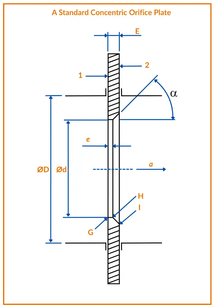
Both ISO 5167 and ASME MFC-3M specify that the thickness of the orifice plate particularly at the bore must meet certain dimensional limits to ensure mechanical strength and accurate flow measurement.
According to these standards, the plate thickness must satisfy the following condition:
The thickness (e) of the orifice plate shall be between:
where:
D = internal diameter of the pipe (mm or in)
e = thickness of the orifice plate (mm or in)
In addition, the thickness should not normally exceed 0.05 D to avoid affecting flow characteristics.
Plate Thickness
Both ISO 5167 and ASME MFC-3M specify that the thickness of the orifice plate must meet defined limits to ensure strength and measurement accuracy.
Plate Thickness Equation
The plate thickness must satisfy the standard relationship between pipe diameter and plate thickness.
Where:
E = Thickness of the orifice plate (mm or in)
For pipe sizes between 50 mm and 64 mm, a plate thickness of up to 3.2 mm is permitted.
Proper thickness selection prevents plate deformation while maintaining accurate flow measurement.
Angle of Bevel
If the plate thickness is greater than the bore thickness, the plate must be beveled on the downstream side. This ensures that the sharp, square edge remains on the upstream side, directly facing the incoming flow.
Maintaining a sharp upstream edge is essential for generating a stable and predictable differential pressure.
The recommended bevel angle (α) is:
45° ± 15°
Proper beveling helps maintain measurement accuracy and compliance with standard guidelines.
Minimum Orifice Diameter
According to the International Organization for Standardization and the American Society of Mechanical Engineers, the orifice (bore) diameter must be equal to or greater than 12.5 mm in all cases.
The American Petroleum Institute specifies a slightly higher minimum of 12.7 mm, mainly to reduce the risk of plugging caused by pipe scale or foreign particles.
This requirement may be relaxed for clean fluid applications.
In addition to meeting the minimum diameter limit, the selected bore must also comply with the recommended beta ratio range, which is discussed in the next section.
Beta or Diameter Ratio
The beta ratio (β) is defined as the ratio between the orifice bore diameter and the internal pipe diameter. It is one of the most important parameters in orifice plate sizing.
Beta Ratio Equation
Where:
β = Beta ratio (unitless)
d = Orifice (bore) diameter mmorinmm or inmmorin
D = Internal pipe diameter mmorinmm or inmmorin
According to ISO and ASME standard, the beta ratio should be within the range of 0.10 to 0.75.
The API recommends a slightly narrower range. It suggests a minimum beta ratio of 0.20, with an upper limit of 0.75 for liquids and 0.70 for gas or steam applications.
In practical industrial applications, a beta ratio between 0.4 and 0.6 is generally considered ideal. This range provides a good balance between measurable differential pressure and acceptable permanent pressure loss.
It is important to note that diameter values are typically measured under actual operating (working) conditions. If measurements are taken under different temperature or pressure conditions, corrections must be applied to account for thermal expansion or contraction of both the pipe and the orifice plate. These adjustments ensure accurate flow calculation under real process conditions.
Orifice Edge
The upstream edge of the orifice bore must be perfectly sharp and square. This sharp edge is critical for generating a stable and predictable differential pressure.
According to standard recommendations, the upstream edge radius must be less than 0.0004d, where:
d = Orifice (bore) diameter
In addition, the angle between the bore and the upstream face must be:
90° ± 0.3°
Maintaining these tight tolerances ensures accurate flow measurement and consistent discharge coefficients.
In contrast, the downstream edge does not require the same strict precision. Since it lies in the separated flow region, its dimensional tolerances are less critical compared to the upstream edge.
What we learn today?
Selecting the correct orifice plate size is essential for accurate and reliable flow measurement. Proper sizing depends on bore diameter, beta ratio, plate thickness, edge geometry, and compliance with standards such as ISO and ASME.
When these parameters are carefully evaluated based on operating conditions, the orifice plate delivers stable performance, predictable differential pressure, and dependable long-term measurement accuracy.
I hope you like above blog. There is no cost associated in sharing the article in your social media. Thanks for Reading !! Happy Learning
