Table of Contents
ToggleNAMUR NE43 Standardization of 4–20mA Signal Levels
In the world of industrial automation, the 4–20mA signal is like a universal language.
Whether you are working with pressure transmitters, flow meters, or level sensors etc this signal is everywhere.
But here is a real question:
What happens when something goes wrong?
How does the system know if the value is truly high… or
if the instrument itself has failed?
This is exactly where the NAMUR NE43 standard plays an important role.
Let us understand in a simple way.
Why Standardization Was Needed
Before the introduction of NAMUR NE43, there was no uniform method to distinguish between a process abnormality and an instrument failure.
For example, if a controller receives a signal above 20mA, it becomes difficult to determine whether:
1. The process value is genuinely high
2. The transmitter has developed a fault
This lack of clarity could lead to incorrect decisions, unnecessary shutdowns, or even safety risks.
To address this issue, a standardized approach was required.
What is NAMUR NE43?
NAMUR (Normenarbeitsgemeinschaft für Mess- und Regeltechnik) is an international user association of automation technology in the process industry, founded in Germany in 1949.
The NAMUR NE43 recommendation defines how a transmitter should indicate abnormal conditions using the 4–20mA signal.
It categorizes signals into clearly defined regions so that control systems can easily interpret them.
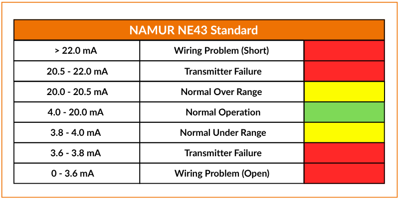
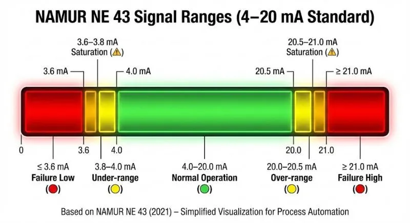
Signal Zones Defined by NAMUR NE43
NAMUR NE43 divides the current signal into three main categories:
1. Normal operating range
2. Saturation (out-of-range)
3. Hardware fault
Each of these zones has a specific meaning and purpose.
Normal Operating Range
The standard operating signal lies between 4mA and 20mA.
Within this range:
1. The transmitter is healthy
2. The process variable is within the calibrated limits
3. The system is operating normally
Any variation within this range represents a valid measurement.
Out-of-Range (Saturation) Signal Levels
In practical situations, process values may exceed the calibrated range of the transmitter.
For example, a tank may overflow or pressure may exceed its design limit.
In such cases, a NAMUR-compliant transmitter does not immediately indicate a fault. Instead, it enters the saturation region.
1. Upper saturation level extends up to 20.5mA
2. Lower saturation level extends down to approximately 3.8mA
These values indicate that the instrument is working correctly, but the process is outside its normal range.
Another important reason for saturation is signal drift over time.
Even a well-calibrated transmitter may slightly deviate after years of operation, resulting in signals like 3.9mA instead of exactly 4mA.
Hardware Fault Signal Levels
Modern smart transmitters are capable of self-diagnostics. They can detect failures such as sensor damage, electronic faults, or internal conversion errors.
When such faults occur, NAMUR NE43 defines two distinct fault signal levels:
1. Downscale fault at 3.6mA or below
2. Upscale fault at 21.0mA or above
These values clearly indicate that the transmitter itself is not functioning correctly.
Fail-Safe Modes in Transmitters
Most transmitters allow configuration of how they respond during a fault condition.
1. Upscale mode sets the output to 21mA when a fault is detected
2. Downscale mode sets the output to 3.6mA
For 2-wire transmitters, it is generally recommended to use upscale mode. This is because loop-powered devices require a minimum current for proper operation, and very low current levels may affect their performance.
For 4-wire transmitters, both modes can be used without any issue since they are not dependent on loop current.
Understanding the Undefined Zones
NAMUR NE43 also defines small transition regions where signals ideally should not occur:
1. Between 3.6mA and 3.8mA
2. Between 20.5mA and 21.0mA
If signals fall within these ranges due to noise or anomalies, the control system should treat them as valid measurements rather than faults.
Interpretation by PLC and DCS Systems
A properly configured control system should be capable of interpreting signals within a range of at least 0 to 22mA.
The logic should be:
1. 4–20mA indicates normal operation
2. 3.8–4mA and 20–20.5mA indicate saturation
3. ≤3.6mA or ≥21mA indicates a hardware fault
To avoid false alarms, the fault signal should persist for at least 4 seconds and for a minimum of two scan cycles before being confirmed.
Control System Response to Fault Conditions
When a fault is detected, the control system can take several actions depending on the process requirements.
1. Adjust or stop production to prevent unsafe conditions
2. Trigger alarms and notify maintenance personnel
3. Switch the affected control loop to manual mode
These actions help in maintaining safety and minimizing downtime.
Importance of NAMUR NE43 in Modern Plants
NAMUR NE43 is widely accepted as a best practice in instrumentation and control systems.
It offers several advantages:
1. Clear distinction between process abnormality and device failure
2. Improved safety and faster fault detection
3. Reduced troubleshooting time
4. Standardization across different manufacturers and systems
Simple Practical Understanding
A simple way to remember NAMUR NE43 is:
1. 4–20mA means everything is normal
2. Slightly beyond this range indicates process abnormality
3. Extreme values such as 3.6mA or 21mA indicate instrument failure
Even a small difference in current carries significant meaning in industrial systems.
Frequently Asked Questions (FAQ)
1. What is NAMUR NE43 standard?
NAMUR NE43 is a recommendation that defines how 4–20mA signals should indicate out-of-range conditions and transmitter faults.
2. What is the normal 4–20mA range?
The normal operating range is from 4mA to 20mA, representing 0% to 100% of the measurement span.
3. What does 3.6mA indicate?
A signal of 3.6mA or lower indicates a hardware fault in downscale mode.
4. What does 21mA indicate?
A signal of 21mA or higher indicates a hardware fault in upscale mode.
5. What is saturation in NAMUR NE43?
Saturation refers to signals slightly outside the normal range, indicating that the process variable is beyond calibrated limits but the instrument is still functioning correctly.
6. Why is 4mA used instead of 0mA?
4mA allows detection of faults such as wire break or power loss, which would result in 0mA.
7. Which fail-safe mode is recommended?
Upscale mode (21mA) is generally recommended for 2-wire transmitters to ensure proper operation.
8. Can PLCs automatically detect NAMUR NE43 signals?
Yes, provided they are properly configured to interpret the defined current ranges.
What we learn today?
The NAMUR NE43 standard brings clarity and intelligence to the widely used 4–20mA signal by clearly defining how transmitters should behave during abnormal and fault conditions.
It ensures that control systems can easily distinguish between a process issue and an instrument failure.
This standard improves plant safety, reduces downtime, and enhances troubleshooting efficiency.
For instrumentation engineers, properly understanding and implementing NAMUR NE43 is not just a recommendation, but a critical step toward building reliable and robust control systems.


I hope you like above blog. There is no cost associated in sharing the article in your social media. Thanks for Reading !! Happy Learning