Table of Contents
ToggleLinear Variable Differential Transformer (LVDT) is a widely used position and displacement measuring device in industrial instrumentation and automation systems.
It is used to measure linear movement of an object and convert that movement into an electrical signal.
Unlike mechanical switches or contact-based sensors, an LVDT works on the principle of electromagnetic induction, which allows accurate measurement without physical contact between moving parts. Because of this construction, LVDTs offer high repeatability, long service life, and stable output, making them suitable for applications such as valve position feedback, actuator monitoring, machine tool alignment, and quality inspection systems.
In this article, we will understand what LVDT is, how it is constructed, how it works, and where it is used in real industrial environments, explained in a clear and practical way.
What are LVDT Sensors?
A Linear Variable Differential Transformer (LVDT) is a sensor used to measure linear displacement or position. It works by converting the linear movement of a core into a corresponding electrical output signal.
The core moves freely inside the coil assembly without touching it, which means there is no mechanical friction or wear during operation. Because of this non-contact construction, LVDT sensors provide consistent accuracy, high resolution, and long operational life.
They are widely used in industrial environments where reliable position measurement is required, even under conditions such as vibration, dust, temperature variation, or continuous operation.
Construction of LVDT
An LVDT consists of a cylindrical former on which three coils are wound. The primary winding is placed at the center of the former, while two secondary windings are placed symmetrically on either side of the primary winding.
The two secondary windings are identified as S1 and S2. Both secondary coils have the same number of turns, but they are wound in opposite directions. Due to this opposite winding arrangement, the output voltage of the LVDT is obtained as the difference between the voltages induced in S1 and S2.
A high-permeability soft iron core is positioned inside the cylindrical former. This core is not fixed and is free to move in a linear to-and-fro direction along the axis of the coils. The position of this movable core determines the amount of magnetic coupling between the primary winding and each secondary winding.
The primary winding is energized using an AC excitation voltage, typically in the range of 5 to 12 V, with an operating frequency generally between 50 Hz and 400 Hz. This AC excitation creates an alternating magnetic field, which induces voltages in the secondary windings depending on the position of the core.

How Does an LVDT Work?
When an LVDT is in operation, its primary winding is energized using a constant-amplitude AC supply. This AC excitation produces an alternating magnetic flux around the primary coil. The movable core transfers this magnetic flux to the two secondary windings, S1 and S2, depending on its axial position inside the coil assembly.
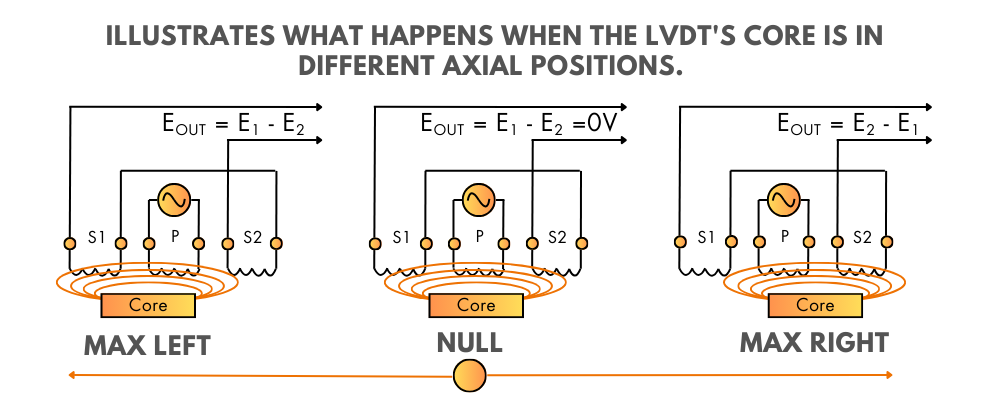
When the core is positioned exactly at the center between the two secondary windings, equal magnetic flux is coupled to both S1 and S2. As a result, the voltages induced in both secondary windings are equal in magnitude. At this position, known as the null position, the differential output voltage of the LVDT is nearly zero.
If the core moves closer to secondary winding S1, a larger portion of the magnetic flux is coupled to S1 and a smaller portion to S2. This causes the voltage induced in S1 to increase while the voltage in S2 decreases, producing a differential output voltage proportional to the displacement.
When the core moves in the opposite direction toward S2, the magnetic coupling to S2 increases and that to S1 decreases, resulting in a differential output voltage with opposite polarity. In this way, both the magnitude and direction of linear displacement are represented by the LVDT output signal.

Types of LVDTs
LVDTs are available in different constructions to suit various installation and application requirements. Selecting the right type depends on how the sensor is mounted, how the core is guided, and how the output signal is processed.
Free-Core (Unguided) LVDT
In a free-core, the movable core is not mechanically attached to the sensor body and moves freely inside the coil assembly. The alignment and guidance of the core are provided by the external mechanical arrangement of the system. This type is commonly used in applications where a guiding mechanism already exists, such as machine tools or test rigs. Free-core LVDTs offer high accuracy but require careful alignment during installation.Captive-Core (Guided) LVDT
A captive-core has the core mechanically guided using internal bearings or rods. This built-in guidance makes installation easier and ensures consistent alignment during operation. Captive-core LVDTs are preferred in rugged industrial environments, mobile equipment, and applications where vibration or misalignment is possible.Spring-Loaded LVDT
In a spring-loaded, an internal spring applies force to the core, pushing it outward to maintain continuous contact with the measured surface. This design is useful in applications such as thickness measurement, dimensional inspection, and position verification, where consistent contact between the sensor and the target is required.AC LVDT and DC LVDT
4.1 AC LVDTs are the traditional form and require external signal conditioning electronics to process the output signal. They are widely used in industrial systems where separate signal conditioning modules are already available.
4.2 DC LVDTs include built-in electronics that provide a conditioned DC output signal directly. These sensors are easier to install, require less wiring, and are suitable for compact systems or applications where space and installation time are limited.
Advantages
Wide Measurement Range
They can measure a wide range of linear displacements, starting from very small movements of about 1.25 mm up to nearly 250 mm. This wide operating range makes them suitable for both precision measurement and general industrial applications.No Frictional Losses
The core moves freely inside a hollow former without touching the coil assembly. Since there is no mechanical contact, frictional losses are eliminated. This improves accuracy and ensures consistent performance over long periods of operation.High Sensitivity and High Output
They have very high sensitivity, typically around 40 V/mm. Due to the relatively high output signal, additional amplification is often not required, which simplifies signal processing and improves measurement reliability.Low Hysteresis
They exhibit very low hysteresis because of their frictionless operation. As a result, the output for the same displacement remains nearly identical during forward and reverse motion, providing excellent repeatability.Low Power Consumption
The power consumption of an LVDT is generally low, around 1 watt. This makes it efficient and suitable for continuous operation in industrial systems.Direct Conversion to Electrical Signal
They directly convert linear displacement into an electrical voltage signal. This electrical output can be easily transmitted, displayed, recorded, or interfaced with control systems.
Disadvantages
Sensitivity to Stray Magnetic Fields
Since LVDTs operate on electromagnetic principles, external magnetic fields can affect their output. Proper shielding and grounding are required to avoid measurement errors.Effect of Vibration and Temperature
LVDT performance can be influenced by mechanical vibrations and temperature variations. In harsh environments, additional mechanical support or compensation techniques may be needed.
Overall, despite these limitations, LVDTs offer better accuracy and reliability when compared to many other inductive displacement transducers.
Applications
Direct Displacement Measurement
LVDTs are widely used to measure linear displacements ranging from a fraction of a millimeter to a few centimeters. In such applications, the LVDT acts as a primary transducer and converts mechanical displacement directly into an electrical signal.Secondary Transducer Applications
LVDTs are also used as secondary transducers in many measurement systems. For example, a Bourdon tube converts pressure into linear displacement, and an LVDT then converts this displacement into an electrical signal. After calibration, this signal represents the pressure of the fluid accurately.
What we learn today?
Linear Variable Differential Transformers remain one of the most reliable solutions for linear displacement measurement in industrial instrumentation.
Their non-contact construction, high accuracy, and repeatable output make them suitable for both laboratory and field applications. Whether used as a primary sensor for direct displacement measurement or as a secondary transducer in pressure, force, or level measurement systems, LVDTs continue to be widely adopted due to their stable performance and long service life.
Understanding their construction, working principle, advantages, and limitations helps engineers select and apply LVDTs correctly in real-world measurement systems.


I hope you like above blog. There is no cost associated in sharing the article in your social media. Thanks for Reading !! Happy Learning