Table of Contents
ToggleElectromagnetic Flow Meter: Introduction
An electromagnetic flow meter is a widely used industrial instrument for measuring the volumetric flow rate of electrically conductive liquids flowing through closed pipelines. These meters are preferred in industries where fluids are dirty, corrosive, abrasive, or contain suspended solids.
Unlike mechanical flow meters, electromagnetic flow meters do not rely on moving parts, pressure drop, or fluid density. Instead, they work on an electrical principle derived from basic physics. This makes them highly reliable, stable, and suitable for long-term operation with minimal maintenance.
To understand why electromagnetic flow meters perform so well in harsh industrial environments, it is important to understand how they work, what they are made of, and where they should be applied.
Fundamental Principle Behind Electromagnetic Flow Measurement
The operating principle of an electromagnetic flow meter is based on Faraday’s Law of Electromagnetic Induction.
According to this law, whenever a conductor moves through a magnetic field, a voltage is induced across that conductor.
In an electromagnetic flow meter:
The liquid acts as the conductor
The magnetic field is generated by coils
The movement of liquid induces a voltage
The induced voltage is proportional to flow velocity
This induced voltage is sensed by electrodes and converted into a flow signal.
Important conditions for this principle to work correctly are:
The fluid must be electrically conductive
The magnetic field must be perpendicular to flow direction
The pipe must be completely full
If these conditions are satisfied, electromagnetic flow measurement becomes highly accurate and repeatable.
Construction of an Electromagnetic Flow Meter
Although the meter appears simple externally, internally it consists of multiple components working together. Each component has a specific role.
Flow Tube and Liner
The flow tube is the part through which the liquid flows. Internally, it is lined with an insulating material to prevent electrical short-circuiting.
The liner performs three critical functions:
Electrically isolates the fluid from the pipe body
Protects the meter from corrosion and abrasion
Ensures stable voltage measurement
Common liner materials include:
PTFE / PFA for aggressive chemicals
Rubber for water and wastewater
Polyurethane for abrasive slurries
Ceramic for high-temperature or highly abrasive services
Magnetic Coils
Magnetic coils are mounted around the flow tube. When energized, they generate a magnetic field across the pipe diameter.
Modern electromagnetic flow meters use pulsed DC excitation, which offers several advantages:
Improved signal stability
Reduced electrical noise
Lower power consumption
Better zero-point stability
The magnetic field is always perpendicular to the flow direction, which is essential for correct voltage induction.
Electrodes
Electrodes are installed directly in contact with the flowing liquid. Their job is to sense the induced voltage.
Key considerations for electrodes include:
Chemical compatibility with the process fluid
Resistance to corrosion and coating
Good electrical conductivity
Common electrode materials include:
Stainless steel for general applications
Hastelloy or Monel for corrosive chemicals
Titanium for chloride-rich fluids
Platinum or tantalum for highly aggressive media
Transmitter or Converter
The transmitter processes the weak voltage signal received from the electrodes.
Its main functions include:
Signal amplification
Noise filtering
Flow calculation
Output signal generation
Typical output options are:
4–20 mA analog signal
Pulse or frequency output
Digital communication such as HART or Modbus
Working of an Electromagnetic Flow Meter
The working sequence of an electromagnetic flow meter can be understood step by step.
The magnetic coils are energized, creating a magnetic field
Conductive liquid flows through the magnetic field
Motion of liquid induces a voltage across the electrodes
The induced voltage increases with flow velocity
The transmitter converts voltage into flow rate
The flow rate is calculated using the relation:
Flow rate = Fluid velocity × Pipe cross-sectional area
Because the induced voltage is directly proportional to velocity, the output signal remains linear across the operating range.
Understanding Faraday’s Law:
Faraday’s law states that when a conductor (the conductive fluid) moves through a magnetic field, a voltage is induced across the conductor.
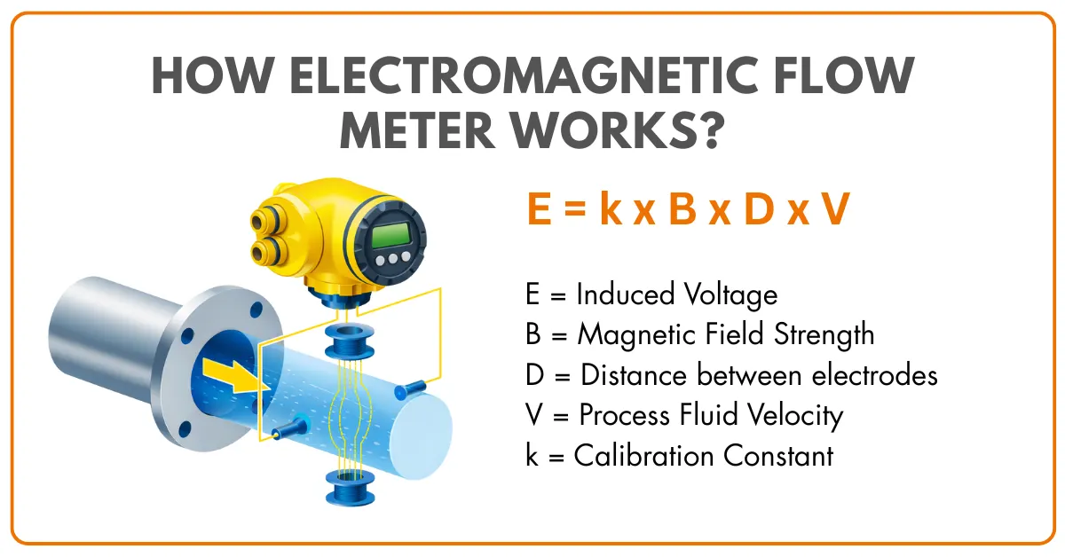
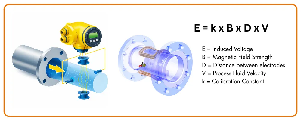
The induced voltage generated in an electromagnetic flow meter is expressed as:
E = B × D × V × k
Where:
E = induced voltage
B = magnetic field strength
D = distance between electrodes
V = fluid velocity
k = calibration constant
Since B, D, and k are constant for a given meter, the equation simplifies to:
Induced voltage ∝ Fluid velocity
This linear behavior is one of the biggest strengths of electromagnetic flow meters.
In the case of an electromagnetic flow meter, the voltage generated is directly proportional to the fluid’s velocity.
The key formula used to calculate the flow rate is Q = A × V, where Q represents the volumetric flow rate, A is the cross-sectional area of the flow tube, and V denotes the average fluid velocity.
Types of Electromagnetic Flow Meters
Electromagnetic flow meters are available in multiple designs depending on application requirements.
Full Bore Electromagnetic Flow Meters
In full bore meters:
The meter diameter matches the pipe diameter
The pipe remains completely full
Maximum accuracy is achieved
These meters are widely used in water, wastewater, and chemical industries.
Insertion Electromagnetic Flow Meters
Insertion meters are used when pipe sizes are very large.
Key characteristics include:
A probe inserted into the pipeline
Lower installation cost
Moderate accuracy compared to full bore meters
They are commonly used for monitoring and energy management applications.
Sanitary Electromagnetic Flow Meters
Sanitary designs are used in hygienic industries.
Their features include:
Smooth internal surfaces
Hygienic process connections
Compatibility with CIP and SIP processes
Advantages of Electromagnetic Flow Meters
Electromagnetic flow meters offer multiple practical advantages.
Major benefits include:
No moving parts, resulting in low maintenance
No obstruction in the flow path
Negligible pressure loss
High accuracy for dirty and abrasive fluids
Insensitivity to viscosity and density changes
Because of these advantages, they are often preferred over mechanical flow meters in harsh process conditions.
Limitations and Practical Constraints
Despite their strengths, electromagnetic flow meters have certain limitations.
Key limitations include:
Only conductive liquids can be measured
Non-conductive fluids like oil and gas cannot be measured
Very low conductivity liquids may cause unstable readings
Improper grounding can affect accuracy
Higher initial cost compared to simple meters
Understanding these constraints helps avoid misapplication.
Installation Guidelines
Correct installation is critical for accurate measurement.
Key installation guidelines include:
Ensure the pipe is always full
Avoid installation at high points in the pipeline
Provide adequate straight pipe lengths
Ensure proper grounding and bonding
Select correct liner and electrode materials
Ignoring installation guidelines often leads to inaccurate readings.

Summary:
Electromagnetic flow meters provide an effective solution for measuring the flow rate of conductive fluids.
By harnessing the principles of electromagnetism, these meters deliver accurate and reliable results across a wide range of applications.
Understanding the basic principles, key formulas, and components of electromagnetic flow meters enables engineers, technicians, and researchers to make informed decisions when selecting, installing, and utilizing these instruments.
Whether you’re working in water management, chemical processing, or any other industry requiring precise flow measurements, electromagnetic flow meters are a valuable tool for optimizing processes and ensuring efficient flow control.
Thanks for reading!! Happy Learning!!


I hope you like above blog. There is no cost associated in sharing the article in your social media. Thanks for reading!! Happy Learning!!