cold junction compensation in thermocouple Temperature Measurement

How to Implement Cold Junction Compensation in Thermocouple Measurements – Formula & Example Calculation

Share:

Thermocouples are one of the most common and reliable temperature sensors used in industrial applications. They are rugged, inexpensive, and can measure a wide range of temperatures. However, thermocouples don’t measure absolute temperature directly they measure temperature difference between two junctions: the hot (measurement) junction and the cold (reference) junction.

To get an accurate temperature reading, we need to know the temperature at both ends. This is where Cold Junction Compensation (CJC) comes into play.

Understanding the Thermocouple Principle

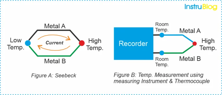
A thermocouple consists of two dissimilar metals joined at one end. When the junctions are at different temperatures, a voltage (called the thermoelectric EMF) is generated due to the Seebeck effect.

This voltage is proportional to the temperature difference between the two junctions and is expressed as:

Where:

  • E = Thermoelectric voltage (in millivolts)
  • α = Seebeck coefficient (µV/°C)
  • Thot = Temperature at the measuring (hot) junction
  • Tcold = Temperature at the reference (cold) junction

Since thermocouples only measure the temperature difference, if we want the absolute temperature at the measuring junction, we must know the cold junction temperature.

Cold Junction Compensation

Thermocouples are temperature sensors that operate on a simple principle. When two dissimilar metals are joined to form a closed circuit, a small voltage called the electromotive force (EMF) is generated whenever there is a temperature difference between the two junctions (see Figure A).

Thanks to their robust design, wide temperature range, and high reliability, thermocouples are widely used for temperature measurement in industrial environments.

By connecting one end of the thermocouple circuit to a measuring device such as a recorder, DCS (Distributed Control System), or PLC (Programmable Logic Controller), the resulting voltage or EMF can be accurately measured to determine the temperature at the sensing point (see Figure B).

The Role of Cold Junction

Historically, the cold junction (reference junction) was kept at 0°C using an ice bath. In that case, the thermocouple output directly corresponded to the hot junction temperature.

But in real-world industrial systems, the cold junction is usually located at the input terminals of the instrument, which are at ambient temperature not 0°C.

Hence, to get the correct hot junction temperature, we must compensate for the actual cold junction temperature. This is called Cold Junction Compensation (CJC).


Why Cold Junction Compensation Is Needed

Let us understand this with an example:

Suppose you are using a Type K thermocouple, and it produces a voltage corresponding to 100°C (with a 0°C reference). But your instrument terminals (cold junction) are actually at 25°C.

The thermocouple doesn’t know this it only generates voltage for the difference between 100°C and 25°C, not between 100°C and 0°C.

Without compensation, your reading would appear 75°C instead of 100°C.

Therefore, CJC ensures your measurement reflects the actual process temperature.


Methods of Cold Junction Compensation

There are three common methods used in instrumentation systems:

a) Ice Bath Reference Method

1) The cold junction is physically maintained at 0°C using an ice-water mixture.

2) Accurate but impractical for industrial environments.

3) Commonly used in laboratory calibration setups.

b) Hardware Compensation Using a Thermistor or RTD

1) A temperature sensor (such as a thermistor or RTD) is placed near the thermocouple terminals.

2) The sensor measures the terminal (cold junction) temperature.

3) The instrument’s microcontroller adds this temperature to the thermocouple reading using stored reference tables or polynomial equations.

c) Software Compensation (Digital Correction)

1) Used in modern digital transmitters and data loggers.

2) The system measures the cold junction temperature electronically.

3) Using calibration tables or NIST thermocouple polynomial equations, it computes the equivalent EMF and corrects the reading mathematically.

Mathematical Implementation of Cold Junction Compensation

Let us go step by step on how to calculate it.

Step 1: Measure the thermocouple output voltage

The thermocouple generates a voltage Emeas corresponding to the temperature difference between hot and cold junctions:

Step 2: Measure cold junction temperature

Using an RTD or thermistor, measure the terminal temperature Tcold.

Step 3: Find the EMF equivalent for cold junction temperature

Use the standard NIST thermocouple tables to find the voltage corresponding to Tcold, say Ecold.

Step 4: Add the voltages

Etotal=Emeas+Ecold
 

Step 5: Convert back to temperature

Finally, using the same thermocouple table, find the temperature corresponding to Etotal.
This is the true hot junction temperature Thot.

Let us take an example

Let’s go through a simple Type K thermocouple example.

Given:

=> Measured thermocouple voltage: Emeas=2.000 mVE

=> Cold junction temperature: Tcold=25°C

Step 1: Find Ecold from thermocouple table

From the NIST Type K table:

At 25°C, Ecold=1.000 mV

Step 2: Calculate total EMF

Step 3: Find corresponding temperature

From the NIST Type K table:

3.000 mV corresponds to approximately 73.5°C

Final Result:
Hot junction temperature = 73.5°C

Without cold junction compensation, the reading would have been only 2.000 mV → about 48°C, which is 25°C lower than the correct value.

Implementation in Modern Instruments

a) Analog Implementation

In analog systems, the cold junction temperature sensor (typically an LM35, AD590, or PT100) provides a voltage proportional to temperature.
This voltage is then summed (using op-amp circuitry) with the thermocouple voltage to simulate the effect of a 0°C reference.

b) Digital Implementation

In microcontroller-based instruments, the process is as follows:

  1. Measure:

  • The thermocouple voltage using an ADC.
  • The cold junction temperature using an onboard sensor.
  1. Convert both readings to millivolts using polynomial equations.

  2. Add them to obtain the equivalent EMF for 0°C reference.

  3. Convert back to temperature using a lookup table or inverse polynomial.

This method provides accurate and automatic cold junction compensation.

Practical Tips for Accurate Cold Junction Compensation

1) Avoid temperature gradients across the connection terminals.

2) Use proper connectors made from thermocouple materials to minimize additional junction errors.

3) Calibrate your system regularly using reference sources.

4) Shield and ground your thermocouple wires to minimize noise interference.

What we learn today?

Cold Junction Compensation is not just a correction it’s an essential step in achieving accurate thermocouple measurements. Without it, your readings could be off by tens of degrees, especially in varying ambient conditions.

By combining precise sensing (RTD or thermistor), NIST-standard tables, and smart software algorithms, modern instruments can provide reliable and automatic compensation ensuring the temperature displayed truly reflects the process temperature.

I hope you like above blog. There is no cost associated in sharing the article in your social media. Thanks for reading!! Happy Learning!!

Leave a Reply

Your email address will not be published. Required fields are marked *

What Is Cascade Control? A Quick Instrumentation Guide Why is the Restriction Orifice Placed Away from Blowdown Valve? 5 Common Pressure Gauge Mistakes Technicians Make 4–20 mA Signal in Instrumentation – The best signal 4 Types of Signals in Instrumentation: AI, AO, DI & DO 100 Flow Measurement Objective Questions and Answers 100 PLC and Automation Objective Questions and Answers