In industrial automation, wiring errors can cause huge issues: incorrect readings, communication failures, equipment damage, and even safety risks.
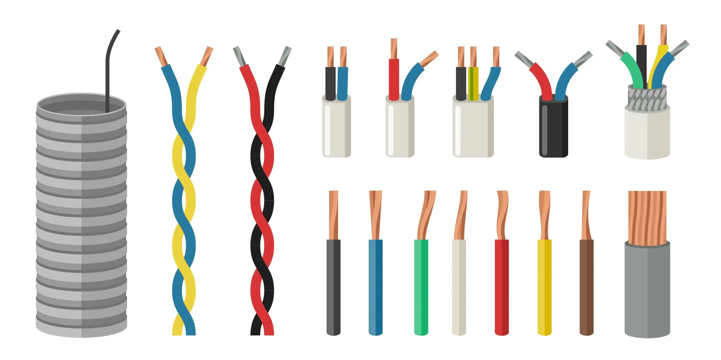
That’s why standard cable color codes and wiring practices are very important for reliable operation & faster troubleshooting.
This guide will help technicians, engineers, and students understand the most common wiring color codes and how to apply them during installation, loop checks, and maintenance.
Table of Contents
ToggleCable Color Codes for Analog Signal Wiring (4–20 mA & 0–10 V)
Analog signals are the traditional way to transmit process values like pressure, temperature, level, or flow between field instruments and control systems.
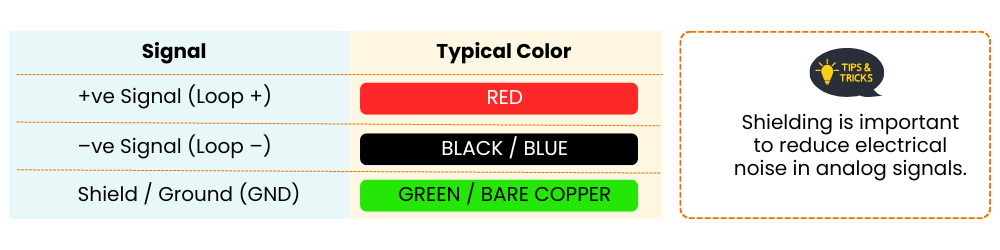
Why Use 4–20 mA?
- Can travel long distances (up to 1000 meters)
- Immune to electrical noise
- Allows loop-powered instruments
- Easy to detect open-loop or wire break (signal falls below 4 mA)
Common Applications:
- Pressure transmitters
- Temperature transmitters
- Flow meters
- Control valves with positioners
Cable Color Codes for RTD Wiring (2-wire, 3-wire & 4-wire)
RTD stands for Resistance Temperature Detector. It measures temperature by detecting the resistance change in a metal (usually platinum).
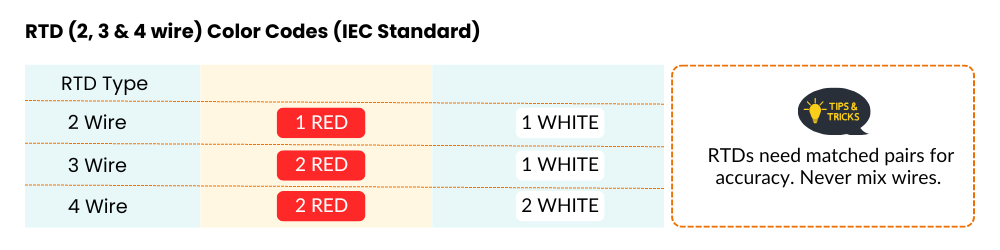
Key Notes
- 3-wire RTDs are most common in industrial applications
- 4-wire RTDs are used for very accurate measurements
- Never mix up leads. It will cause incorrect temperature readings
Cable Color Codes for Thermocouple Wiring
A thermocouple uses two different metals joined at one end to create a temperature-dependent voltage.
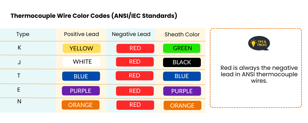

Tips:
- Use matching extension wires — don’t mix types!
- Red wire is always the negative (-) in ANSI thermocouples.
- For long cable runs, use shielded twisted pair with thermocouple-grade wire.
Cable Color Codes for Digital Communication Cables
Digital protocols are used for smart transmitters, controllers, and remote monitoring systems. They carry both data and device diagnostics.
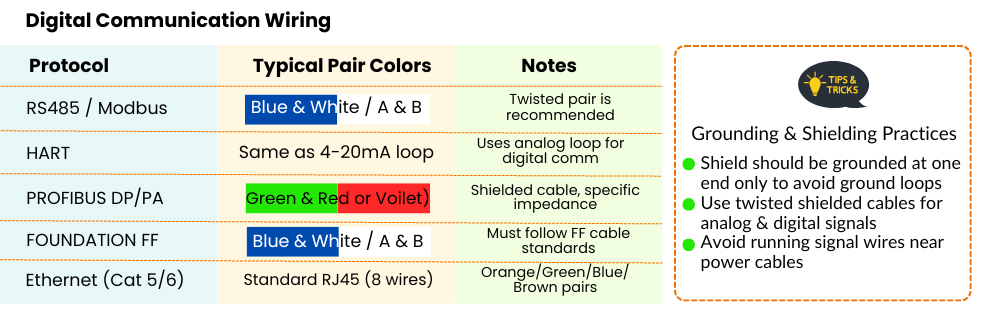
Grounding & Shielding
Why Is It Important?
Grounding and shielding protect signals from electromagnetic interference (EMI) and help prevent false readings or system faults.
Best Practices:
- Connect shield to ground at one end only
- Avoid sharing the same conduit for signal and power cables
- Use metal cable glands for shield termination at panel entry
- Follow Ex zone grounding rules in hazardous areas
Tips for Technicians
🧷 Label Everything
Always label both ends of every cable – saves time during maintenance and avoids mix-ups.
📐 Follow Project Drawings
Stick to wiring diagrams and termination schedules. If unsure, ask — don’t guess.
📸 Document Your Work
Take photos of the terminal blocks before closing the junction box or panel. It helps during future servicing.
⚠️ Check Before Powering Up
Use a multimeter to verify correct polarity, loop continuity, and grounding before energizing instruments.
Summary
Correct cable color coding and wiring practices are the backbone of a stable, accurate, and safe instrumentation system. Whether you are a technician doing a new install or an engineer troubleshooting a field device, following proper standards saves time and prevents costly mistakes.
📌 Bookmark or print this guide. Better wiring starts with better knowledge.

I hope you like above blog. There is no cost associated in sharing the article in your social media. Thanks for reading!! Happy Learning!!