Table of Contents
ToggleIn industries like oil and gas, petrochemical, and power generation, pressure control and safety are very important.
Two important components that ensure safe operation are the Blowdown Valve (BDV) and the Restriction Orifice (RO).
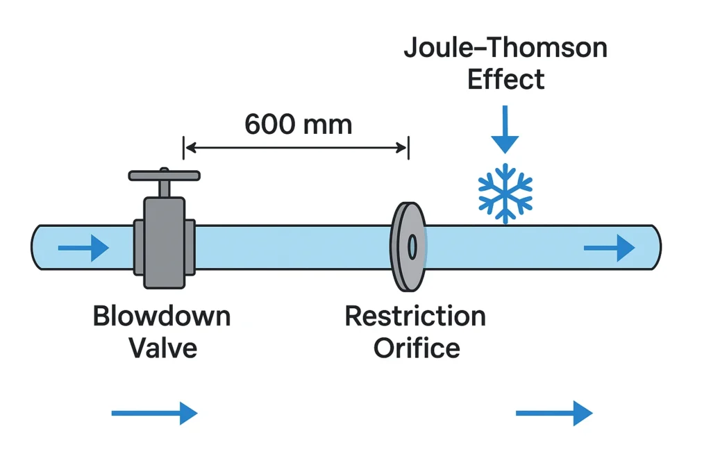
If you look at a blowdown system’s piping, you will find the restriction orifice placed some distance usually around 600 mm or more away from the blowdown valve.
This spacing is not random; it plays a key role in maintaining safety, performance, and reliability.
Let us understand this.
What is a Restriction Orifice?
A Restriction Orifice (RO) is a plate with a hole in it, fitted into a pipeline to limit the flow or reduce pressure.
When gas or liquid flows through this small opening:
- Its velocity increases
- Its pressure drops
This allows engineers to control how fast the fluid moves and how much pressure is released.
Unlike an orifice used for flow measurement, a restriction orifice is designed to handle high pressure drops and prevent too much flow downstream.
What is a Blowdown Valve?
A Blowdown Valve (BDV) is a valve used to depressurize equipment during emergencies or planned shutdowns. It helps safely vent high-pressure gases or liquids into a low-pressure system (like a flare header).
When the BDV opens, the restriction orifice downstream controls the rate of pressure release, protecting both equipment and personnel.
Why Keep a Distance Between BDV and RO?
You might wonder why not install the restriction orifice right after the blowdown valve?
The reason is: Safety, temperature control, and flow stability.
A small section of pipe (called a spool piece) usually 600 mm long is kept between them to solve several issues.
Let us look at each one.

1. The Joule Thomson Effect – Preventing Freezing
The biggest reason for this spacing is the Joule-Thomson (JT) effect.
When a high-pressure gas expands suddenly (as it passes through the restriction orifice), its temperature drops sharply sometimes below freezing.
This cooling can travel back toward the blowdown valve, causing it to freeze if the two are too close. A frozen valve might get stuck open or closed, creating safety hazards.
By keeping a 600 mm gap, the cold gas gets a chance to warm up slightly, preventing the valve from freezing.
In short: The spacing acts as a thermal buffer.
2. Avoiding Flashing, Noise, and Vibrations
When a high-pressure liquid passes into a low-pressure zone, part of it may vaporize suddenly and this is called flashing.
Flashing causes:
1) Excessive noise
2) Vibrations
3) And sometimes cavitation, which can damage metal parts.
Placing the orifice a short distance away from the BDV allows the fluid to expand more smoothly, reducing turbulence and preventing these harmful effects.
In short: The gap helps achieve a smoother, quieter pressure drop.
3. Smoother Flow and Controlled Pressure Drop
The main pressure reduction in a blowdown system occurs at the restriction orifice, not the valve.
If the orifice is too close to the valve:
1) The flow leaving the valve is turbulent
2) The orifice may experience uneven flow
3) Pressure drop becomes unpredictable
The 600 mm spool helps straighten the flow, ensuring that the orifice experiences uniform, laminar flow. This results in a steady pressure drop and prevents damage to the orifice or downstream piping.
In short: The spacing ensures predictable and stable flow behavior.
4. Reducing Erosion and Cavitation
When high-velocity fluids pass through an orifice, erosion can occur on the orifice plate and pipe walls.
If pressure drops are too large, cavitation (the formation and collapse of vapor bubbles) can also happen, damaging the system.
By allowing a short section of pipe between the valve and the orifice, the flow velocity reduces gradually, minimizing erosion and cavitation risk.
In short: The spacing extends the life of both valve and orifice.
5. Maintaining System Integrity
This small distance also reduces mechanical stress in the pipeline.
A gradual pressure drop means less strain on fittings, joints, and welds.
In high-pressure systems (like refineries and gas processing plants), such design practices help prevent cracks, leaks, or fatigue failures.
In short: The spacing keeps the whole system healthy and safe.
How Much Distance Should Be Kept?
A minimum of 600 mm is a common engineering guideline.
However, the actual distance can depend on:
1) Type of fluid: Gas, liquid, or steam behave differently.
2) Operating pressure and temperature: Higher pressures need more spacing.
3) Piping layout: Space constraints may require adjustments.
4) Safety considerations: In some cases, insulation or heating jackets are added to prevent freezing.
Types of Restriction Orifice Plates
There are several designs of ROs used in industries:
| Type | Description | Best For |
|---|---|---|
| Single-stage RO | One hole, simple design | Moderate pressure drops |
| Multi-hole RO | Several small holes | Reduces noise and vibration |
| Multi-stage RO | Multiple plates in series | Very high pressure drops |
| Conical RO | Cone-shaped bore | Smooth flow and less turbulence |
What we learn today?
Keeping a restriction orifice at a distance from a blowdown valve is a small but crucial design choice in process engineering.
That 600 mm spool piece ensures:
1) Protection against freezing (JT effect)
2) Reduced noise, flashing, and vibrations
3) Stable and smooth pressure control
4) Prevention of erosion and cavitation
5) Improved system integrity and safety
This setup helps the system release pressure safely, avoid damage, and operate smoothly even under extreme industrial conditions.
I hope you like above blog. There is no cost associated in sharing the article in your social media. Thanks for reading!! Happy Learning!!


