
Table of Contents
ToggleSignals in Instrumentation and Process Control
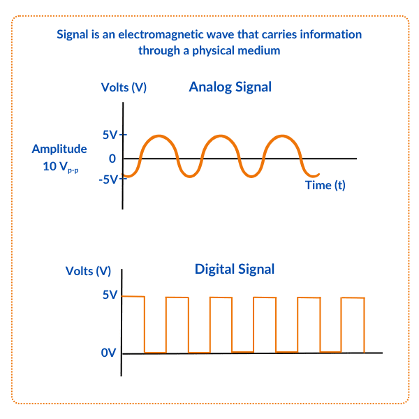
In instrumentation and control, signals are the language through which machines communicate. Just like humans use speech or text to share ideas, industrial systems use signals to transfer information from one point to another.
Signals in instrumentation represents data, often carried in the form of voltage or current. These signals can be analog smooth and continuous, like temperature or pressure readings or digital, which are ON/OFF values, like switches and alarms.
By encoding, transmitting, and decoding signals, control systems ensure that sensors, controllers, and final control elements work together seamlessly to keep industrial processes running safely and efficiently.
What are different types of Signals in Instrumentation
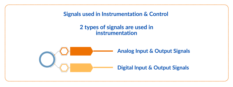
There are 2 types of signals in instrumentation and process control used.
1) Analog Input, Analog Output Signals
2) Digital Input, Digital Output Signals
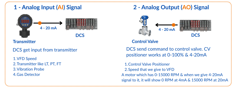
Analog Input (AI) Signals in Instrumentation
An Analog Input (AI) is like the ears of your control system. It listens to what’s happening in the plant. These signals come from sensors that measure real-world values such as temperature, pressure, level, or flow. Since these values can vary smoothly over time (not just ON/OFF), they are sent as continuous signals like 4–20 mA current or 0–10 V voltage. In short, AI is how your system “hears” the process conditions.
Analog Output (AO) Signals in Instrumentation
An Analog Output (AO) works like the voice of the control system. It talks back to the equipment. Once the controller makes a decision, it sends out an analog signal to control devices such as valves, dampers, or speed drives. For example, if a flow needs to increase, the AO signal may tell a valve to open more gradually. Just like AI, these are continuous signals, but instead of receiving, AO is about sending instructions out.
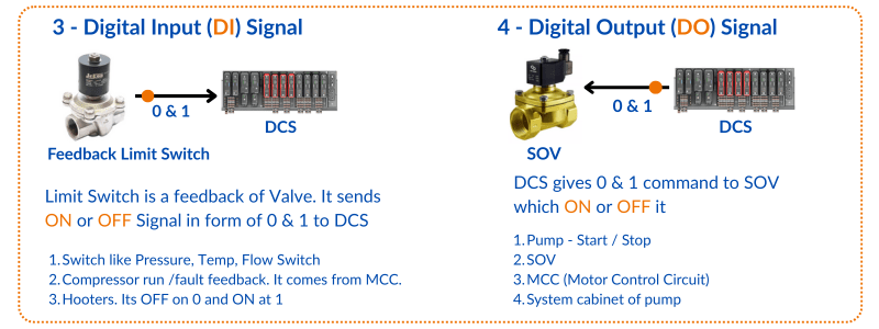
Digital Input (DI) Signals in Instrumentation
A Digital Input (DI) is like a simple light switch. It only tells the system YES or NO, ON or OFF. These signals come from devices such as push buttons, limit switches, pressure switches, or proximity sensors.
They do not carry detailed values but provide clear status updates like “the motor is ON” or “the tank is full.”
DI is how the system knows about events happening in binary form.
Digital Output (DO) Signals in Instrumentation
A Digital Output (DO) is like flipping a switch from the controller’s side. It sends an ON/OFF signal to start or stop a device. Typical examples include turning on a motor, sounding an alarm, or switching a relay.
Unlike AO, which is smooth and variable, DO is straightforward. Either the system activates something or it doesn’t. It is the controller’s way of giving direct commands to the field.
Best Practices for Analog Signals (AI & AO)
- Always use shielded twisted pair cables to minimize electrical noise.
- Follow the 4–20 mA standard instead of 0–10 V wherever possible, as current signals are less prone to voltage drop over long distances.
- Calibrate transmitters and final control elements regularly to avoid scaling errors.
- Keep analog wiring separate from high voltage power lines to reduce EMI (Electromagnetic Interference).
Tips for Reliable Digital Signals (DI & DO)
- Use optocouplers or isolation relays to protect the PLC/DCS from voltage spikes.
- Ensure proper debouncing for mechanical switches, otherwise the input may read false ON/OFF states.
- For critical safety applications (like ESD systems), always use fail-safe wiring (e.g., Normally Closed circuits).
- Label all digital I/O wiring clearly to simplify troubleshooting during plant downtime.
Troubleshooting Signal Problems
- Fluctuating AI signals: Check for loose terminals, grounding issues, or EMI sources like VFDs nearby.
- No AO response: Verify scaling in the PLC/DCS output card and check valve positioner calibration.
- DI not detecting: Inspect the field switch and cable continuity before suspecting the input card.
- DO not energizing device: Measure coil resistance of the relay or motor contactor and confirm the output card rating.
Difference between analog and digital signals in instrumentation
Please see below the difference between analog and digital signals used in instrumentation.
| Feature | Analog Signals | Digital Signals |
|---|---|---|
| Nature | Continuous – vary smoothly over time | Discrete – exist in two states (0/1, ON/OFF) |
| Representation | Voltage or current changes continuously (e.g., 4–20 mA, 0–10 V) | Binary pulses (HIGH/LOW) |
| Data Type | Represents real-world values like temperature, pressure, flow | Represents status information like switch ON/OFF |
| Precision | High detail, infinite possible values | Limited detail, only defined states |
| Susceptibility | More affected by noise and interference | Less prone to noise due to clear ON/OFF levels |
| Processing | Harder to store and process without conversion | Easy to process and store in digital systems |
| Devices Used | Sensors, transmitters, control valves | Switches, relays, alarms, push buttons |
| Use in Automation | For measurement and continuous control (AI, AO) | For status monitoring and discrete actions (DI, DO) |
Web Stories


I hope you like above blog. There is no cost associated in sharing the article in your social media. Thanks for reading!! Happy Learning!!