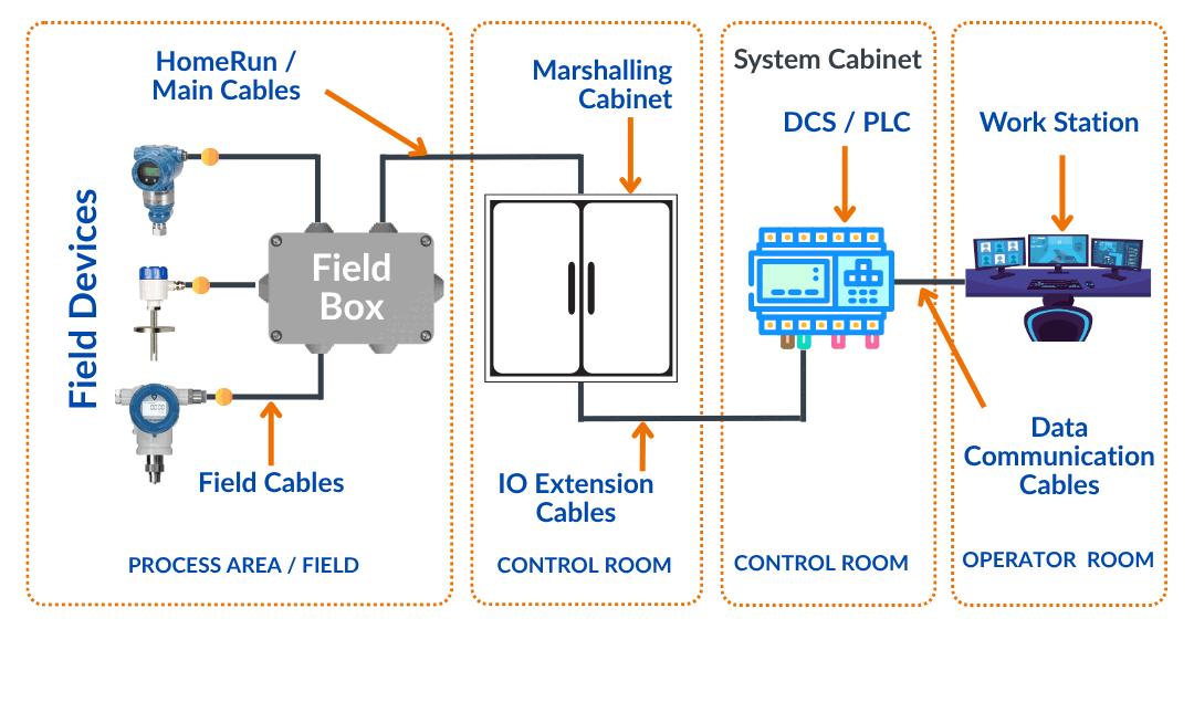
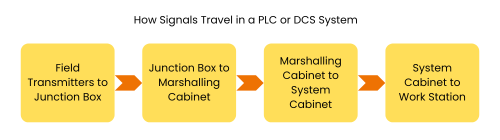
PLC Wiring is very important topic. A PLC connection shows how signals travel step-by-step—from the field transmitters, through the junction box and marshalling cabinet, into the system cabinet, and finally to the Human-Machine Interface (HMI), where operators can see and control the process on a screen.
Table of Contents
TogglePLC Connection
In this explanation, we are only talking about traditional 4-20mA analog input devices to help you easily understand the basic idea while doing PLC Wiring.
How Signals Travel in a PLC or DCS System
In a process plant, there are thousands of field transmitters installed to measure things like pressure, temperature, flow, etc. It’s not practical to run separate cables from each transmitter all the way to the control room.
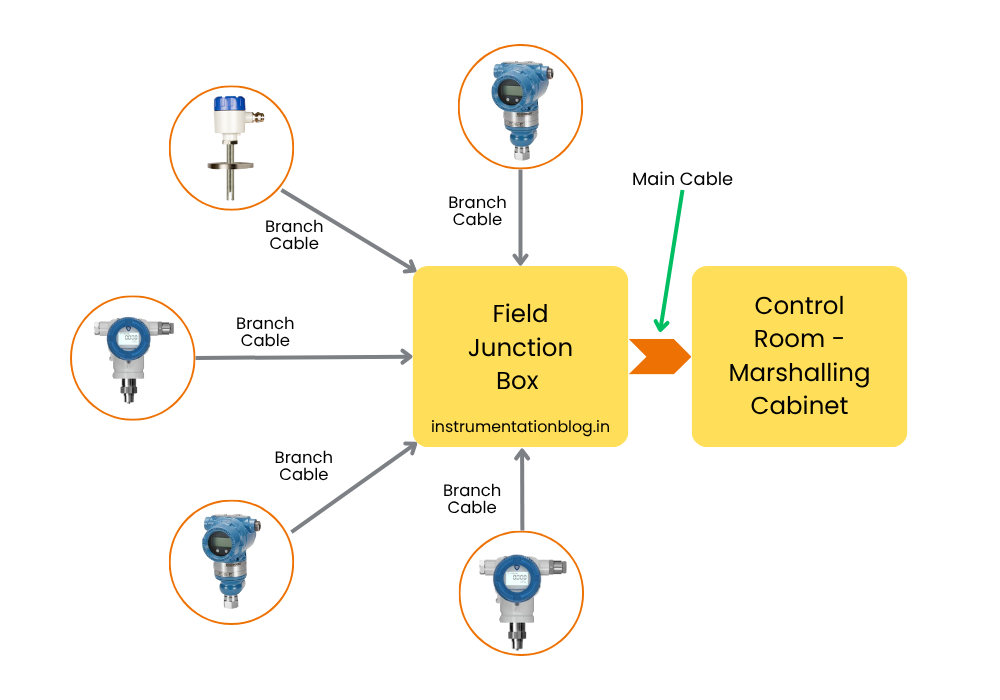
So, based on standard design practices, a group of transmitters is connected to a Field Junction Box (JB).
The cables that connect each transmitter to the junction box are called Branch Cables or Field Cables. Usually, we use one pair cable for each signal (one wire for positive, one for negative).
In the example below, five transmitters are connected to a junction box using five separate branch cables.
Now, to send these five signals from the junction box to the control room, we need at least a 5-pair cable. But for future needs (spares), we usually go for a 6-pair or 12-pair cable.
This larger cable is called a Main Cable or Home Run Cable. It connects the junction box in the field to the Marshalling Cabinet in the control room.
So, instead of running many small cables all the way, we use one big main cable and that solves the problem.
In a process plant, we have many Junction Boxes, and each one is connected to several field devices (like transmitters or sensors).
Let us say there are 100 junction boxes in total.
This means there are 100 main cables coming from the field to the control room — one from each junction box.
Now, it is not practical for any technician to connect all these 100 main cables directly to the analog input/output (I/O) cards in the control system.
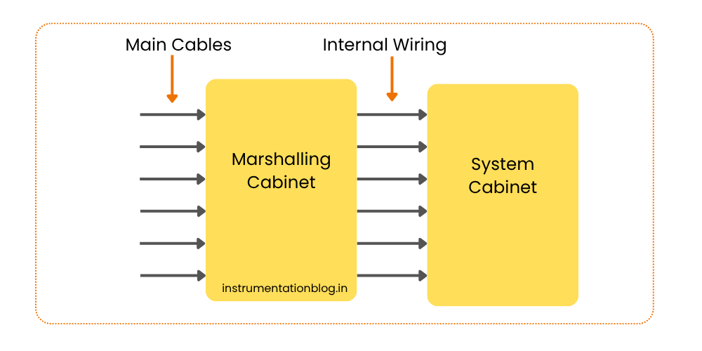
To manage this better, we use a Marshalling Cabinet.
What does a Marshalling Cabinet do?
- It helps to organize and terminate all the incoming main cables from the field.
- Then, it re-routes or re-distributes the signals using neat internal wiring.
- These internal wires go from the Marshalling Cabinet to the System Cabinet, where the I/O cards are installed.
This setup keeps the wiring organized and makes maintenance easier.
How Signals Flow from Marshalling to System Cabinet
The System Cabinet contains important parts like the Processor (CPU), Analog Input Cards, Analog Output Cards, Communication Cards, and more.
After the main cables from the field are connected to the Marshalling Cabinet, we need to send those signals to the correct Analog Input channels in the System Cabinet.
To do this, we use internal wiring to connect the Marshalling Cabinet to the System Cabinet.
Once connected, the Analog Input Cards receive the 4-20mA signals from the field devices. These cards then convert the analog signals into digital signals (binary codes).
These digital signals are then sent to the Processor (CPU). The processor works according to the program or instructions stored in it.
The processor may also have a built-in or separate Ethernet communication link, which helps in sending the process data to the workstation (HMI), so the operator can see and monitor the measurements.
DCS DeltaV System Architecture Explanation | Hardware Components
Summary – Understanding PLC/DCS Signal Flow and Wiring
In a process plant, field devices send 4-20mA signals to nearby junction boxes. From there, main cables carry these signals to the marshalling cabinet in the control room. The marshalling cabinet organizes the wiring and connects to the system cabinet using internal wiring.
Inside the system cabinet, analog input cards convert the signals to digital form and send them to the processor (CPU). The processor works as per the program and shares the data with the workstation (HMI), where the operator can monitor and control the process.


I hope you like above blog. There is no cost associated in sharing the article in your social media. Thanks for reading!! Happy Learning!!