
A capacitor rarely fails the same way twice across different technologies, knowing which failure mode belongs to which type is what separates a quick diagnosis from hours spent chasing the wrong suspect.
Electrolytic vs Ceramic vs Tantalum Capacitor Failure Modes differ by construction, electrolytics dry out slowly, ceramics crack suddenly, and tantalums can short and overheat if pushed past their safe voltage margin.
This builds on the general capacitor types article already on this site, but focuses specifically on how each type actually fails in service rather than how it is built.
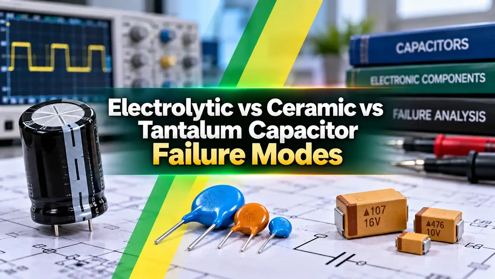
Electrolytic vs Ceramic vs Tantalum Capacitor Failure Modes
Every capacitor eventually reaches the end of its useful life, but the path it takes to get there depends heavily on its internal construction and the dielectric material holding the charge.
An aluminum electrolytic capacitor relies on a liquid or gel electrolyte that can slowly evaporate, a ceramic multilayer capacitor relies on a brittle stacked dielectric that can crack, and a tantalum capacitor relies on an extremely thin oxide layer that can break down under stress.
Understanding Electrolytic vs Ceramic vs Tantalum Capacitor Failure Modes lets an engineer pick the right technology for a given environment and read early warning signs before a failure takes down the rest of a circuit.
How Electrolytic Capacitors Fail
The electrolyte inside an aluminum capacitor evaporates gradually through its end seals over years of operation, a process that speeds up dramatically at higher ambient or self heating temperatures.
As the electrolyte dries, equivalent series resistance climbs and capacitance drifts downward, often losing ten to forty percent of its original value before the part is finally pulled from service.
Rising ESR under ripple current generates more internal heat, which then accelerates the very electrolyte loss causing the problem in the first place, a feedback loop that ends in bulging or vented cans.
How Ceramic Capacitors Fail
A multilayer ceramic capacitor is mechanically brittle, and the most common real world failure is a hairline crack caused by board flexure, a drop, or excessive force during hand soldering or rework.
That crack can bridge internal electrode layers, turning a capacitor into an intermittent or permanent short circuit that may not show up until the board flexes again months later in the field.
Class two and class three ceramic dielectrics also lose capacitance under applied DC voltage, sometimes losing more than half their rated value well before any physical crack ever forms.
How Tantalum Capacitors Fail
A tantalum capacitor's dielectric is an extremely thin oxide layer only a few nanometers thick, and tiny manufacturing defects in that layer can grow into a conductive path when the part sees a voltage surge.
Because tantalum metal itself burns readily once ignited, a shorting tantalum capacitor can generate enough localized heat to smoke, char, or in rare cases flame, unlike a typical electrolytic or ceramic failure.
Polymer tantalum variants fail open rather than short under the same stress, trading a small loss of function for a dramatically safer failure outcome in the field.
The Three Failure Modes at a Glance
| Type | Primary Failure Mode | Common Trigger | Typical Result |
|---|---|---|---|
| Electrolytic | Electrolyte dry out | Age, heat, high ripple current | ESR rise, bulging, vented can |
| Ceramic (MLCC) | Mechanical crack | Board flex, thermal shock, solder stress | Intermittent or hard short |
| Tantalum | Dielectric breakdown | Voltage surge, reverse voltage, high inrush | Hard short, possible overheating |
Preventing Premature Capacitor Failure
Where Each Failure Mode Shows Up First
Common Mistakes That Trigger Early Failure
Diagnosing a Failed Capacitor in the Field
A visual inspection catches the easy cases first, a bulging or vented electrolytic can, a scorched tantalum, or a hairline crack under a ceramic terminal visible with magnification and good lighting.
When nothing looks obviously wrong, an in circuit ESR meter is usually the fastest next step, since a rising ESR reading on an electrolytic often shows up well before capacitance drifts far enough to matter.
A capacitance meter comparing a suspect part against its datasheet value, ideally desoldered to remove any parallel circuit effects, confirms drift on either an electrolytic or a DC biased ceramic capacitor.
Testing Methods by Capacitor Type
Thermal imaging under normal operating load is worth the extra step on any board with a repeat field failure, since a capacitor running noticeably hotter than its neighbors is very often the root cause.
Keeping a simple failure log, noting capacitor type, location, ambient conditions, and symptom, turns individual field returns into a pattern that points straight at a design margin problem rather than a batch of bad parts.
Fails Open vs Fails Short
Fails Short (Standard Tantalum, Cracked Ceramic)
Can pull down a rail hard, draw excess current, and in the tantalum case generate real heat or smoke.
Fails Open (Polymer Tantalum, Dried Out Electrolytic)
Loses filtering or decoupling function gradually, usually shows up as noise or instability rather than fire risk.
Neither outcome is automatically acceptable, a design that cannot tolerate any loss of decoupling needs redundancy regardless of which failure mode the chosen capacitor technology favors.
Choosing a Capacitor Technology With Failure Modes in Mind
Bulk energy storage on a power supply rail, where some gradual capacitance loss over years is tolerable, still favors electrolytic capacitors for their high capacitance per rupee and predictable, non violent failure path.
Space constrained, vibration heavy designs favor ceramic capacitors for bulk decoupling, provided the layout keeps larger case sizes away from flex prone board edges and mounting hardware.
High reliability or safety critical circuits that genuinely need a tantalum capacitor's stability and low ESR should specify a polymer variant wherever the fail open behavior is available, rather than defaulting to standard wet tantalum.
A Simple Decision Checklist
None of these questions replace a proper reliability calculation for a specific application, but they catch the majority of preventable field failures traced back to picking a capacitor technology on cost alone.
Watch: A Real Capacitor Failure Mode
Capacitor Failure Modes FAQs
Related Articles on This Site
- Capacitor Types Explained
- How Decoupling Capacitors Work
- What Is Capacitance
- Essential PCB Design Rules
- PCB Design Fundamentals
External References
What We Learn Today
- Electrolytic capacitors fail slowly through electrolyte dry out, ceramics fail suddenly through mechanical cracking.
- Tantalum capacitors can fail short with real heat risk unless voltage is properly derated.
- Matching the derating rule to each capacitor type is the single biggest lever for reliability.