Table of Contents
TogglePressure Tappings in Orifice Plate: Introduction
When we talk about differential pressure flow measurement, the orifice plate is often the first device that comes to mind. It is simple, reliable, and widely used across industries like oil & gas, water treatment, power plants, and chemical processing.
But here is something many beginners ignore.
The accuracy of an orifice plate system does not depend only on the plate itself. It heavily depends on how and where the pressure is tapped from the pipe.
This is where Pressure Tappings in Orifice Plate become extremely important.
In this article, we will clearly understand:
What pressure tappings are
Why their location matters
Types of pressure taps used with orifice plates
When to use which tapping type
Practical selection guidance
Let us begin from the basics.
What Are Pressure Tappings in Orifice Plate?
An orifice plate works on Bernoulli’s principle.
When fluid passes through the restriction (orifice), velocity increases and pressure decreases. By measuring the pressure difference between two points (upstream and downstream), we can calculate the flow rate.
But how do we measure this pressure difference?
We drill small holes in the pipe or flange and connect impulse lines to a differential pressure transmitter. These holes are called pressure tappings.
So in simple words:
Pressure tappings are small openings in the pipe that allow us to measure high and low pressure across the orifice plate.
Their position determines:
The magnitude of differential pressure
Measurement accuracy
Calibration constant
Compliance with standards like ISO 5167 and ASME
Even a small change in tapping location can change the discharge coefficient and final flow reading.
That is why understanding pressure tappings in orifice plate is critical.
Why Tapping Location Matters So Much?
After fluid passes through an orifice plate:
Pressure drops suddenly at the restriction.
The lowest pressure occurs slightly downstream at the vena contracta.
Pressure gradually recovers further downstream.
Now imagine this.
If you take the downstream pressure reading at the wrong point, you will not measure the correct differential pressure. That directly affects flow calculation.
Different industries and standards allow different tapping locations. Each has its own advantages and limitations.
Let us now explore each type in detail.
Types of Pressure Tappings in Orifice Plate
There are six commonly referenced pressure tapping types associated with orifice flow measurement:
Flange Taps
Vena Contracta Taps
Radius Taps
Pipe Taps (Full Flow Taps)
Corner Taps
Elbow Taps
We will understand each one clearly.
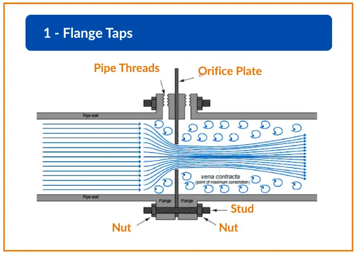
1. Flange Taps
Flange taps are the most widely used pressure tappings in orifice plate installations.
They are positioned:
One inch upstream of the orifice plate
One inch downstream of the orifice plate
For pipe sizes greater than 2 inches, this one-inch rule applies regardless of pipe diameter.
Important points:
Not recommended for pipe sizes below 1.5 inches
Generally avoided below 2 inches
Very common in North America
Why are they popular?
Easy to machine in flanges
Repeatable geometry
Well standardized in ISO and ASME
In real industrial installations, if you open an orifice meter run, most likely you will see flange taps.
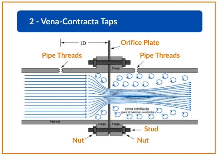
2. Vena Contracta Taps
After fluid passes through the orifice, the narrowest jet forms slightly downstream. This point is called the vena contracta.
Here:
Pressure is minimum
Velocity is maximum
In vena contracta tapping:
Upstream tap is placed one pipe diameter upstream
Downstream tap is placed at the point of minimum pressure
These taps aim to capture the maximum possible differential pressure.
However:
Exact vena contracta location varies with beta ratio
Not as standardized as flange taps
Installation accuracy becomes critical
They are sometimes preferred in smaller pipe diameters where maximizing DP is necessary.
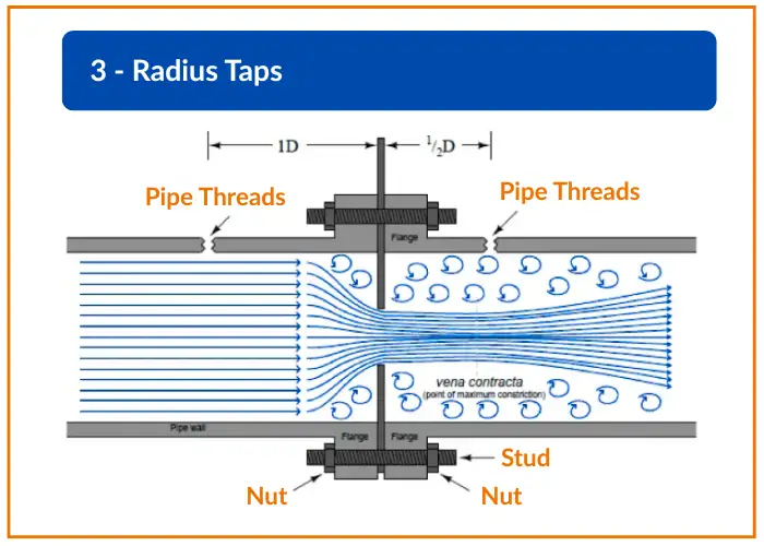
3. Radius Taps
Radius taps are more formalized and geometrically defined.
Their positions are:
Upstream tap at 1 pipe diameter (1D) upstream
Downstream tap at 0.5 pipe diameter (0.5D) downstream
These taps are typically recommended for:
Pipe sizes 6 inches or larger
Situations requiring better standard compliance
Compared to flange taps:
They are located further away
Less influenced by flange machining tolerance
In high accuracy flow measurement systems, radius taps are often preferred.
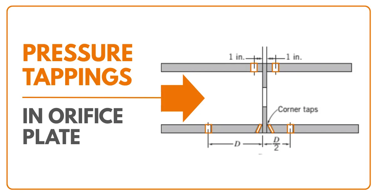
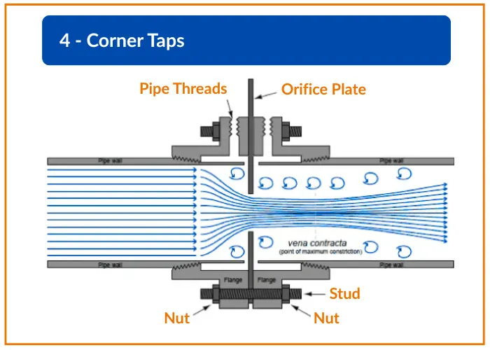
4. Corner Taps
Corner taps are positioned directly at the faces of the orifice plate.
In other words:
Upstream tap is located at the upstream face
Downstream tap is located at the downstream face
They are very similar to flange taps but physically located at the plate edge.
Usage differences:
In Europe, corner taps are used for all pipe diameters
In North America, mainly used for pipe sizes below 2 inches
Advantages:
Very compact design
Suitable for small line sizes
Good repeatability
If you are working on small bore piping, corner taps are usually the preferred choice.
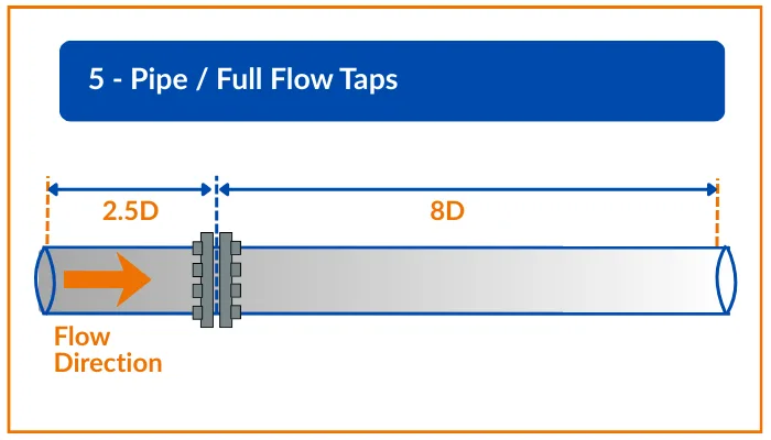
5. Pipe Taps (Full Flow Taps)
Pipe taps are located further away from the orifice plate.
Typical locations:
2.5 pipe diameters upstream
8 pipe diameters downstream
Because they are not close to the orifice flange:
Exact location tolerance is less critical
However, measurement error can be higher
Pressure recovery may influence reading
These taps were more common in older installations.
In modern standardized systems, flange or corner taps are more preferred.
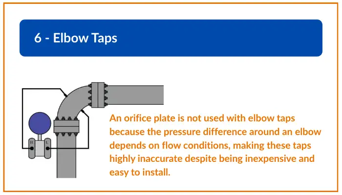
6. Elbow Taps
Elbow taps are different from the previous types.
Here:
No orifice plate is used
Pressure difference is measured across an elbow
When fluid flows around an elbow:
Centrifugal force creates pressure difference
Outer side pressure is higher
Inner side pressure is lower
Although:
They are inexpensive
Easy to install
They are:
Not highly accurate
Very sensitive to flow profile
Not recommended for custody transfer
Elbow taps are generally used where cost is more important than high accuracy.
Comparison of Pressure Tappings in Orifice Plate
Let us summarize key practical differences:
Flange Taps – Most common and standardized
Corner Taps – Best for small diameter pipes
Radius Taps – Used in larger pipes with better geometry control
Vena Contracta Taps – Capture maximum DP but less standardized
Pipe Taps – Older design, more measurement variation
Elbow Taps – Low cost but lower accuracy
How to Select the Right Pressure Tapping?
Selecting pressure tappings in orifice plate depends on:
Pipe Diameter
Industry Standard Requirement
Required Accuracy
Space Availability
Type of Fluid
For example:
If pipe size is below 2 inches, corner taps are preferred.
If pipe size is above 6 inches and high accuracy is required, radius taps are recommended.
If following ISO 5167 strictly, tapping type must match calculation constants.
Always remember:
Changing tapping type changes discharge coefficient.
You cannot replace flange taps with pipe taps without recalculation.
What we learn today?
Pressure tappings in orifice plate systems may look like a small detail.
But in reality, they define the entire measurement accuracy.
Many times, engineers focus only on beta ratio and plate thickness. They forget tapping geometry.
In instrumentation, precision is not only about expensive transmitters.
It is about correct positioning.
If you understand pressure tapping types clearly, you can:
Design better meter runs
Avoid calibration issues
Reduce measurement uncertainty
Improve plant performance
Flow measurement is science.
Pressure tapping location is geometry.
And geometry defines accuracy.


I hope you like above blog. There is no cost associated in sharing the article in your social media. Thanks for Reading !! Happy Learning