Table of Contents
ToggleIn industrial automation and process control, transmitters are used to convert physical process variables into electrical signals that can be understood by control systems.
One topic that often creates confusion for students, technicians, and even junior engineers is the difference between 2 wire transmitters and 4 wire transmitters.
Although both types are used for measurement and signal transmission, their power supply requirements, wiring arrangements, and typical applications are quite different.
In this article, we will take a practical look at 2 wire and 4 wire transmitters, explain where each type is commonly used, and why one may be selected over the other in plant installations.
We will also explore basic transmitter wiring configurations and clearly understand how transmitters are connected to PLC analog input cards in industrial control systems.
What is a Transmitter?
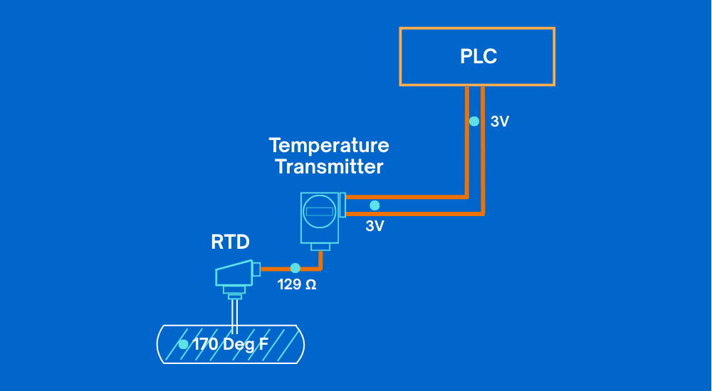
A transmitter is an instrument used to convert the small electrical signal generated by a sensor into a standardized signal that represents the process variable being measured. Sensors on their own usually produce very weak signals, such as millivolts or changes in resistance, which cannot be sent directly to a control system over long distances.
The transmitter conditions this small signal and converts it into a usable output that can be reliably transmitted to a PLC, DCS, or other control devices.
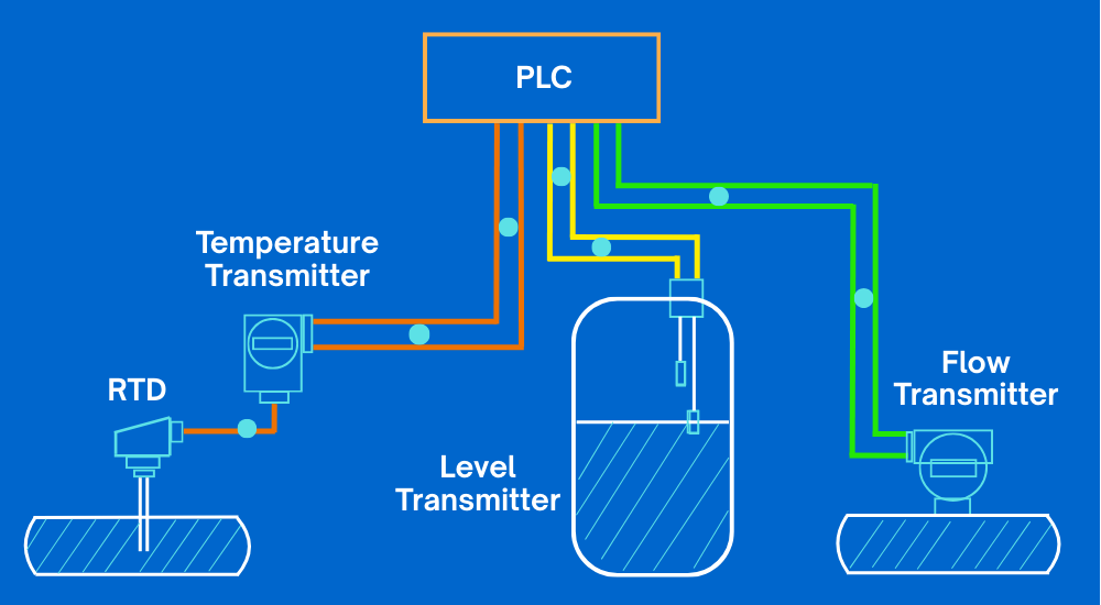
Transmitters are available in many physical forms and designs depending on the application. They can be mounted in the field, inside control panels, or directly on process equipment.
Transmitters can work with a wide range of sensors, including pressure sensors, temperature sensors, level sensors and flow sensors.
Regardless of the sensor type, the main purpose of the transmitter is the same to ensure the measured process value is converted into a stable and accurate electrical signal that the control system can read and act upon.
Transmitter Output Signals
The output signal from a transmitter, which represents the measured process variable, can be either a voltage signal or a current signal.
This output signal is what carries the measurement information from the field transmitter to the control system, such as a PLC or DCS.
The type of output signal used depends on the transmitter design, application requirements, and installation conditions.

Transmitter Analog Output Loops
A transmitter analog output loop is the complete electrical path used to transmit the measurement signal from the field transmitter to the control system.
This loop typically includes the transmitter itself, a power supply, and a receiving device such as a PLC or DCS analog input. The loop ensures that the measured process value is continuously sent to the control system in the form of an analog signal.
Like any measuring instrument, a transmitter requires electrical power to operate. However, the way this power is supplied depends on the type of transmitter being used.
Some transmitters receive power through the same wires that carry the signal, while others use a separate power connection. This brings us to an important question whether the transmitter is a 2-wire type or a 4-wire type.
The actual wiring arrangement between the transmitter, power supply, and receiving device is determined by this classification. Understanding this difference is essential for correct installation and troubleshooting and we will examine both wiring methods in detail in the following sections.
Advantages of 4 Wire Transmitters
Before comparing 2 wire and 4 wire transmitters, it is important to understand the type of output signal used by most transmitters. As discussed earlier, transmitter outputs can be either voltage or current. In industrial environments, current output signals are used far more frequently than voltage signals.
One major reason for this preference is the effect of cable length. When a voltage signal is transmitted over long distances, voltage drops can occur due to resistance in the connecting wires.
These voltage losses can lead to inaccurate readings at the PLC or DCS input, especially in large plants where transmitters may be installed far from the control room.
In a current loop, this problem is largely avoided. Basic electrical principles show that the current flowing in a series circuit remains the same at all points in the loop.
This means that even if the cable length is long, the current reaching the PLC remains unchanged. As a result, the measurement signal remains accurate and reliable, making current-based transmitters especially 4 wire transmitters well suited for demanding industrial applications.
4-Wire Transmitters
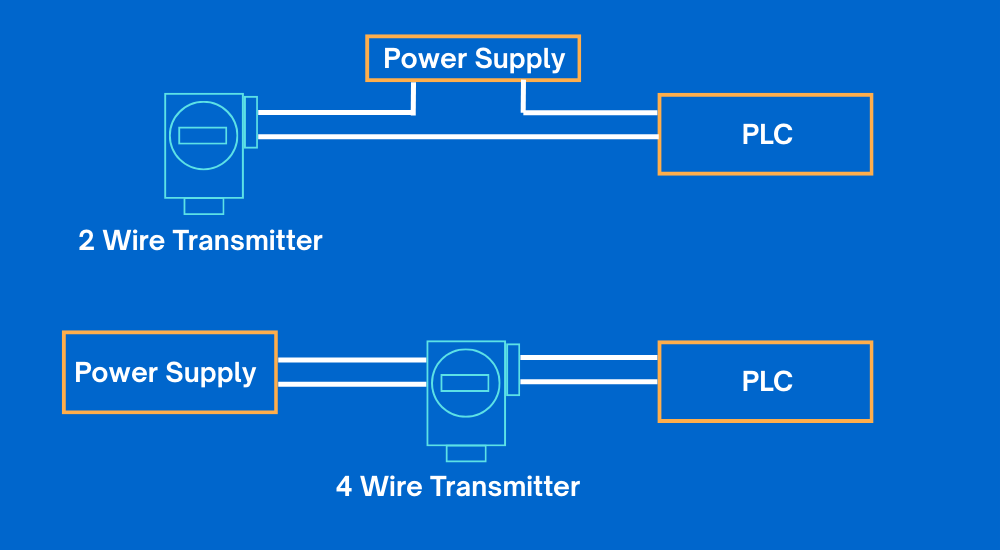
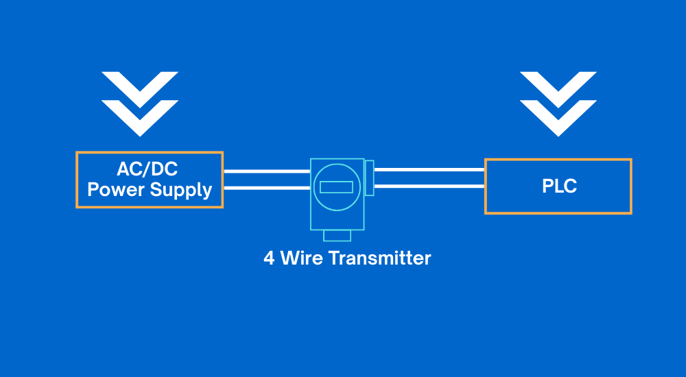
Now that the basic concepts are clear, let us look more closely at how a 4 wire transmitter is connected and how it operates in an actual installation. As the name suggests, a 4 wire transmitter uses four separate electrical connections to function properly.
Out of these four wires, two wires are dedicated to supplying power to the transmitter, while the other two wires are used only for the output signal. The signal wires carry the measured process value to the PLC or DCS analog input, while the power wires ensure that the transmitter has a stable and independent power source.
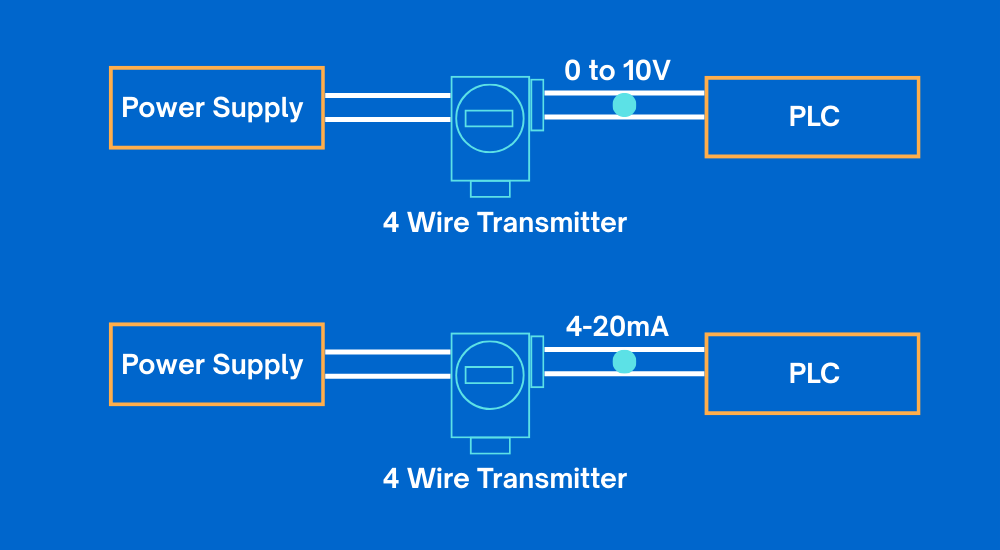
Depending on the transmitter design and manufacturer, the external power supply can be either AC or DC. This separation of power and signal wiring allows 4-wire transmitters to deliver strong and stable output signals, even in applications where higher power consumption or voltage output is required.
2-Wire Transmitters
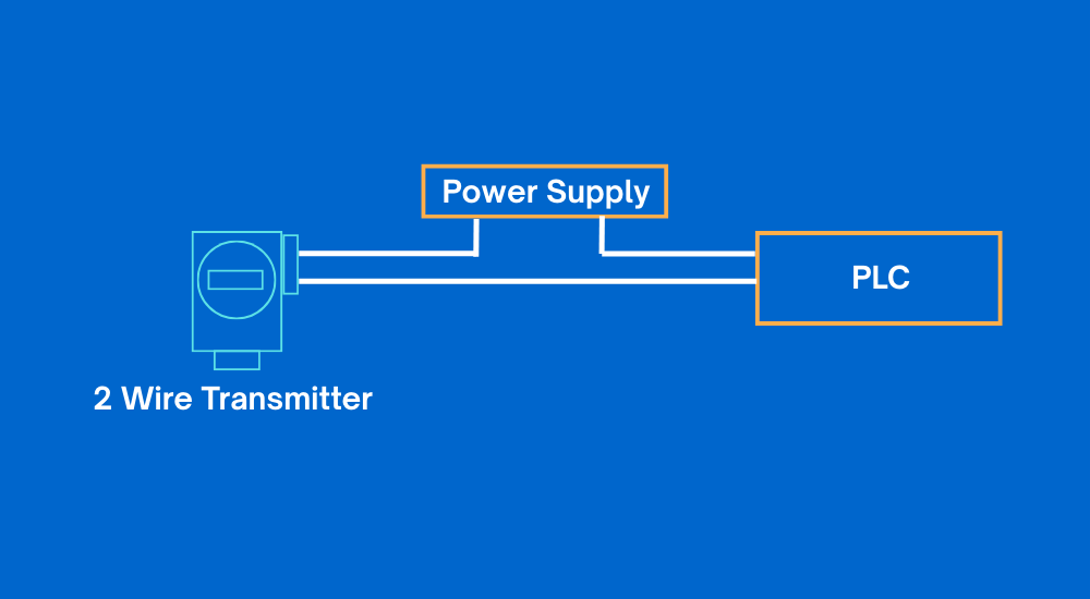
As the name suggests, a 2 wire transmitter uses only two electrical wires for its operation. These two wires perform a dual function, which is the main characteristic that differentiates a 2 wire transmitter from a 4 wire transmitter.
In a 2 wire current loop, the transmitter, the DC power supply, and the PLC analog input are all connected in series. The same pair of wires is used to supply power to the transmitter and to carry the measurement signal back to the PLC. In other words, the transmitter draws its operating power from the current loop itself, while the loop current simultaneously represents the measured process variable.
This simple wiring arrangement makes 2-wire transmitters widely used in industrial applications where low power consumption, fewer cables, and straightforward installation are preferred.
Two-Wire Loop-Powered Transmitters
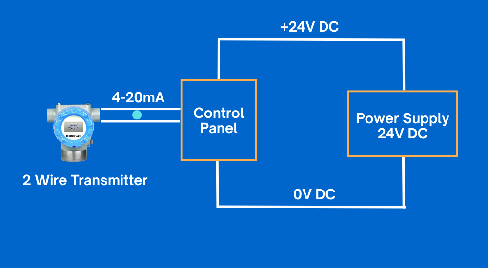
In a two-wire loop-powered transmitter configuration, both the operating power and the 4–20 mA output signal are transmitted over the same pair of wires between the field transmitter and the control panel. This means no separate power cable is required, making the wiring simple and cost-effective.
However, not all transmitters can operate in this manner. Only transmitters that are specifically designed to be loop-powered can function correctly in a two-wire configuration. These transmitters are engineered to consume very low power so they can operate entirely from the energy available in the 4–20 mA current loop.
What we learn today?
In this article, we explored the basic working concepts of transmitters and clearly understood the differences between 2-wire and 4-wire transmitters.
We learned how a transmitter converts a sensor’s small output into a usable electrical signal and how this signal is transmitted to a PLC or DCS using an analog output loop.
The role of current signals, especially the 4–20 mA loop, was explained along with the reasons why current transmission is preferred in industrial environments. We also discussed how 4-wire transmitters use separate power and signal connections, while 2-wire transmitters operate using a single loop for both power and signal transmission.
Understanding these differences helps in selecting the correct transmitter type, designing proper wiring configurations, and ensuring reliable signal transmission in real plant applications.


I hope you like above blog. There is no cost associated in sharing the article in your social media. Thanks for Reading !! Happy Learning