Table of Contents
ToggleSafety Relay: Introduction
One of the most important components in an electrical control panel is a relay.
A relay is an electromechanical switch that opens or closes its contacts when an electrical signal is applied. In simple terms, it acts as an interface between two electrical circuits while keeping them electrically isolated.
Relays are available in many types, each designed for a specific purpose and operating condition. Among them, safety relays stand out due to their dedicated role in protecting people, machines, and processes.
A safety relay is specially designed to perform critical safety functions with high reliability and predictable behavior. Despite their compact size, these relays offer excellent dependability and are widely used in applications where failure is not an option.
Safety relays are very important in environments such as industrial machinery, manufacturing plants, and power facilities, where ensuring safe operation is essential.
This article provides a clear overview of what a safety relay is, how it works, and why a standard electromechanical relay is not considered safe for safety-related applications.
What Is a Safety Relay?
A safety relay is a relay specifically designed for use in industrial and machine safety applications. Unlike standard control relays, safety relays are built to perform critical safety functions where human protection and equipment safety are essential.
The main purpose of a safety relay is to reduce risk to an acceptable level when a hazardous situation occurs. It continuously monitors defined safety inputs and, when an abnormal condition or fault is detected, it triggers a reliable and predictable safety response.
Safety relays are designed to be easy to integrate, highly dependable, and capable of long service life while meeting internationally recognized safety standards. Their internal design ensures that faults are detected and unsafe conditions do not go unnoticed.
key functions performed by a safety relay
Safe stop of machine motion
The relay ensures that machine movement is stopped in a controlled and safe manner during emergency situations.Monitoring of movable guards and doors
It verifies the correct position of safety gates, guards, and access doors before allowing machine operation.Emergency stop control
Safety relays process emergency stop signals and ensure immediate and safe shutdown of hazardous motion.Interruption of hazardous movements during access
They prevent closing or dangerous movements when an operator accesses a protected area.
Because of these functions, safety relays are widely used in industrial machinery, manufacturing plants, and power generation facilities, where safety-related failures can have serious consequences.
Working Principle of a Safety Relay
The working principle of a safety relay is based on continuous fault detection and reliable shutdown logic. It constantly checks the integrity of the safety circuit to ensure that unsafe conditions are identified immediately.
Detection of wiring and actuator faults
The safety relay sends electrical signals through the connected safety circuit to monitor the condition of wiring, contactors, and actuators. Any wire break, loose connection, or actuator failure is detected by monitoring the current flow in the circuit.Mechanically linked contact monitoring
Safety relays use mechanically linked normally open (NO) and normally closed (NC) contacts. If an NO contact becomes welded and remains closed, the corresponding NC contact cannot close. This mechanical relationship allows the relay to detect welded contacts and prevent unsafe operation.Prevention of hidden failures
Because the relay continuously checks both input and output conditions, faults cannot remain unnoticed. This ensures that dangerous failures do not accumulate over time without detection.Reliable emergency shutdown
When an unsafe condition is detected, the safety relay immediately switches to a safe state. This results in a fast and controlled shutdown of hazardous machine movement.Continuous monitoring of safety devices
Safety relays constantly monitor signals from connected safety devices such as emergency stop buttons, safety gates, and interlock switches, ensuring that safety functions remain active throughout operation.
Fault Detection in a Safety Relay
Safety relays are designed to detect multiple fault conditions to ensure reliable and safe operation. Their fault detection logic continuously checks the safety circuit and connected components to prevent dangerous failures.
Detection of wiring faults
Safety relays monitor current flow by sending electrical signals through the safety wiring. If a wire break, loose connection, or open circuit occurs, the relay immediately detects the fault and switches to a safe state.Detection of welded or faulty contacts
By supervising contact feedback, safety relays can identify welded contact sets or contactors that fail to open or close correctly. This prevents hidden faults that could compromise the safety function.Detection of faulty safety actuators
Malfunctioning safety devices such as emergency stop buttons, interlock switches, or safety gates are detected when their signals do not behave as expected. The relay recognizes abnormal conditions and prevents unsafe operation.Detection of timing-related faults
Safety relays also monitor the timing of redundant safety contacts. If contact sets do not change state within a predefined time window, the relay interprets this as a fault and disables automatic reset functions.Ensuring consistent and dependable safety operation
By combining wiring supervision, contact monitoring, actuator checking, and timing control, safety relays provide a high level of reliability across a wide range of industrial safety applications.
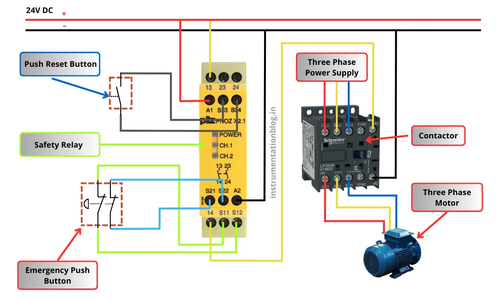
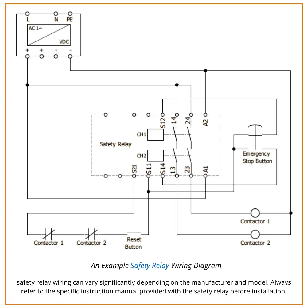
An Example Safety Relay Wiring Diagram
Below is a basic example of a typical safety relay wiring arrangement. Keep in mind that safety relay wiring can vary significantly depending on the manufacturer and model. Always refer to the specific instruction manual provided with the safety relay before installation.
To better understand the schematic, the following key points are important.
Power supply to the safety relay
The safety relay and contactors are powered using a 24 VDC supply. This supply is connected directly to the A1 and A2 terminals of the safety relay, providing operating power to the internal logic and output circuits.Emergency stop (E-Stop) circuit
The emergency stop button uses two mechanically linked normally closed contacts. This dual-contact design supports redundancy, which is a fundamental requirement in safety systems. A pulsed signal from terminal S11 passes through both E-Stop contacts and returns to terminals S12 and S14. When the E-Stop is pressed, both contacts open simultaneously, interrupting the signal and triggering a safety shutdown.Safety output section
Terminals 14 and 24 serve as the supply inputs for the safety output circuits. These terminals are connected directly to the power source. When all safety conditions are satisfied, the safety relay closes its internal force-guided and redundant output contacts, allowing power to flow to terminals 13 and 23. These outputs energize the downstream contactors.Contactor control
The safety relay outputs are connected in a dual-channel configuration to two separate contactors. These contactors are typically wired in series to control the motor or hazardous load, ensuring that a single failure cannot result in unsafe operation.Feedback monitoring loop
The feedback loop continuously monitors the status of the contactors. Normally closed, force-guided auxiliary contacts from each contactor are wired in series and returned to the safety relay at terminal S21. This loop allows the relay to detect faults such as welded or stuck contactor contacts. Depending on the relay design, the loop may be statically monitored or periodically tested using diagnostic pulses.Reset function
If the safety relay enters a tripped state, a reset button is used to restore normal operation. The reset signal passes through the contactor feedback loop, ensuring that the relay can only be reset once all safety conditions are confirmed and the contactors are in a safe state.
Force-guided contacts are mechanically linked so that all contacts move together. If one contact becomes welded or stuck, the remaining contacts cannot change state, allowing the safety relay to detect the fault reliably.
Why Is a Normal Electromechanical Relay Not Considered Safe?
A normal electromechanical relay is not suitable for safety-critical applications because its design and operating characteristics do not provide the reliability, fault detection, and fail-safe behavior required in modern safety systems.
The key reasons are explained below.
1. Mechanical wear and contact welding
Normal electromechanical relays operate using mechanical movement of metal contacts. Over time, repeated opening and closing of these contacts leads to mechanical wear.
During switching, electrical arcing can occur at the contact surfaces. This arcing may cause the contacts to weld together, especially under high current or frequent switching conditions. If contact welding occurs, the relay may fail to open when required.
In a safety scenario—such as when an emergency stop button is pressed—a welded relay contact may continue supplying power to the machine. This can allow hazardous motion to continue, placing operators and equipment at serious risk.
2. Limited reliability and service life
Electromechanical relays have a finite mechanical life, typically rated in millions of switching operations. While this may appear sufficient on paper, real industrial environments often involve:
Frequent switching cycles
Harsh electrical conditions
Continuous daily operation
In applications with hundreds of switching operations per day, the practical service life of a normal relay may reduce to 3–5 years or less. As the relay ages, the likelihood of unpredictable failures increases, which is unacceptable for safety-related functions.
3. No built-in fault detection
Standard electromechanical relays do not provide internal monitoring or feedback mechanisms. They cannot detect conditions such as:
Welded or stuck contacts
Internal mechanical failures
Loss of control integrity
Because of this, faults can remain hidden until a dangerous situation occurs. Safety systems require immediate fault detection, which normal relays cannot provide.
4. Non-compliance with safety standards
Many national and international safety standards do not permit the use of simple relays or contactors for safety functions in hazardous machinery.
Standards used in regions such as Europe and North America require safety devices to:
Detect faults automatically
Fail in a predictable and safe manner
Maintain safety integrity over time
Normal electromechanical relays do not meet these requirements and are therefore not approved for safety applications.
5. Absence of redundancy and fail-safe design
Safety systems rely on redundancy and fail-safe behavior to ensure that a single failure does not lead to a hazardous condition. Normal relays are typically single-channel devices with no redundancy.
A single internal failure can result in complete loss of the safety function, which is unacceptable in safety-critical environments.
Safety Relay vs Normal Relay
Although safety relays and normal electromechanical relays may appear similar at first glance, they are designed for very different purposes. The table below highlights the key differences between the two.
| Parameter | Safety Relay | Normal Relay (General Relay) |
|---|---|---|
| Primary Purpose | Designed specifically to perform safety-related functions in industrial and machine safety systems | Used as an electrically operated switch for general control and automation tasks |
| Typical Application | Machine safety, risk reduction, personnel protection | Control of loads using low-power control signals |
| Physical Size | Usually available in larger modular widths (e.g., 17.5 mm, 22.5 mm) | Typically smaller and more compact |
| Contact Design | Uses force-guided (positively guided) contacts to ensure fault detection | Uses standard contact arrangements including common (C) contacts |
| Fault Detection Capability | Capable of detecting welded contacts and internal failures | No built-in fault detection |
| Color Identification | Commonly yellow for easy identification in safety circuits | No standard color requirement |
| Functional Integration | Combines safety switching, monitoring, indication, and diagnostics | Performs basic switching only |
| Reliability Requirement | Designed for high reliability and predictable failure behavior | Reliability depends mainly on mechanical life |
| Standards Compliance | Certified for use in safety-related applications | Not certified for safety functions |
| Typical Cost | Higher cost due to redundancy and safety certification | Lower cost and widely used in control circuits |
FAQs: Safety Relay vs Normal Relay
1. What is the main difference between a safety relay and a normal relay?
The main difference is in their purpose. A safety relay is designed specifically to perform safety-related functions such as emergency stop control and fault detection. A normal relay is intended for general switching and control tasks and is not designed to protect people or machinery.
2. How does the functionality of a safety relay differ from a normal relay?
Safety relays include built-in monitoring, redundancy, and fault detection features to ensure reliable operation during critical safety events. Normal relays perform simple electrical switching and do not monitor their own condition or detect internal faults.
3. Why are safety relays usually larger than normal relays?
Safety relays are often physically larger because they contain additional internal components such as redundant circuits, force-guided contacts, and diagnostic logic. Normal relays have a simpler construction, allowing them to be smaller and more compact.
4. Why are safety relays more expensive than normal relays?
The higher cost of safety relays is due to their specialized design, certified safety components, redundancy, and compliance with international safety standards. Normal relays are less complex and therefore more economical.
5. Where are safety relays typically used?
Safety relays are used in applications where human safety and risk reduction are critical. Common examples include industrial machinery, automated production lines, robots, presses, and hazardous operations.
6. Where are normal relays commonly used?
Normal relays are widely used in automation and control circuits for tasks such as switching motors, lamps, and control signals. They are suitable where safety-critical functions are not involved.
7. Can a normal relay replace a safety relay in safety applications?
No. Normal relays are not designed or certified for safety functions. Using a normal relay in a safety application can lead to undetected failures and unsafe conditions, which is why safety relays are mandatory in such systems.


I hope you like above blog. There is no cost associated in sharing the article in your social media. Thanks for Reading !! Happy Learning