Table of Contents
ToggleToday we will learn basic parts of a control valve.
Control valves are one of the most important final control elements used in industrial process control systems. They directly regulate the flow of liquids, gases, or steam by responding to signals from controllers, ensuring that process variables such as flow, pressure, level, and temperature remain within the desired limits.
To understand how a control valve works and how to select or troubleshoot one correctly, it is essential to first understand its basic construction.
In this article, we will learn the basic parts of a control valve, explain their functions, types and show how each component contributes to accurate and reliable process control.
What is a Control Valve?
A valve is a mechanical device used to control the flow and pressure of fluids within a piping system or industrial process. By opening, closing, or partially obstructing the flow path, a valve helps maintain safe and efficient operation of the process.
Depending on the application, a valve can perform one or more of the following functions:
Stopping and starting fluid flow
Valves are used to completely shut off or allow fluid flow during normal operation, maintenance, or emergency conditions.Varying (throttling) the flow rate
Some valves regulate flow by partially opening or closing, allowing precise control of the fluid quantity passing through the system.Controlling the direction of flow
Directional valves guide the fluid along a specific path, ensuring it flows to the correct equipment or process section.Regulating downstream pressure
Pressure-regulating valves maintain a desired pressure level downstream, protecting equipment and ensuring stable process conditions.Relieving excess pressure
Safety and relief valves protect piping and components by automatically releasing excess pressure when safe limits are exceeded.
There are many valve designs and types available, each engineered to perform one or more of these functions. With a wide range of materials, sizes, and operating principles, valves are designed to safely handle diverse industrial applications across oil & gas, power, chemical, water, and manufacturing industries.
Basic Parts of Control Valves
Regardless of the type or application, all control valves are built using a common set of basic components. These parts work together to regulate fluid flow, pressure, and process conditions accurately and safely. Understanding these components is essential for proper valve selection, operation, and maintenance.
A control valve is broadly divided into two main sections:
Actuator Part
Valve Body Part
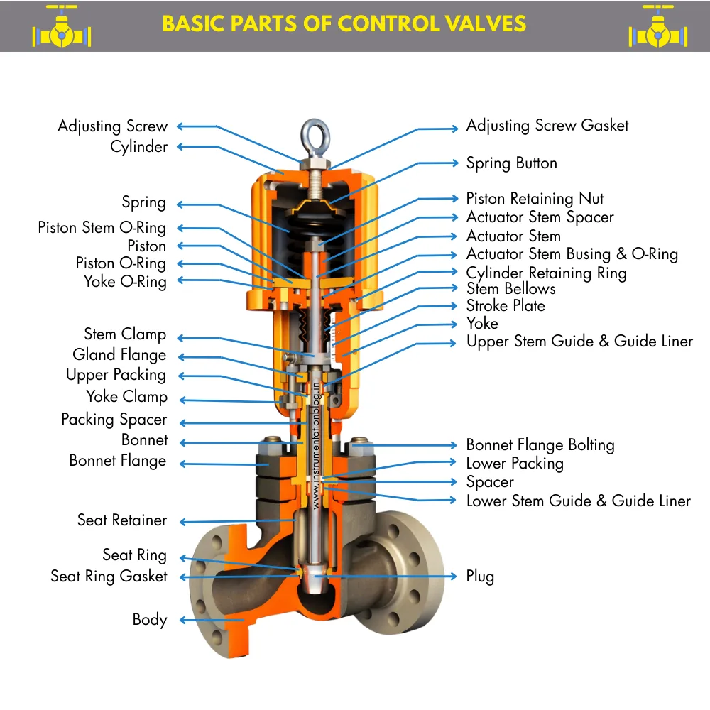
Actuator Part
The actuator is the driving element of a control valve.
It receives a control signal from the controller and converts it into mechanical motion to position the valve plug. In industrial applications, actuators are commonly classified as pneumatic, electric (motorized), or hydraulic.
Pneumatic actuators are the most widely used due to their simplicity, reliability, and suitability for hazardous areas.
A pneumatic actuator operates using compressed air and typically has a simple and robust construction, making maintenance easier. The main components of a pneumatic actuator are explained below.
Rain Cap
The rain cap protects the actuator from rainwater, dust, and debris. It prevents moisture and contaminants from entering the actuator housing, ensuring reliable operation and longer service life, especially in outdoor installations.Eye Bolt
The eye bolt is provided for lifting and handling the valve assembly safely during installation, removal, or maintenance activities.Diaphragm
The diaphragm is a flexible element that converts air pressure into mechanical force. When air pressure is applied, the diaphragm moves and transfers force to the diaphragm plate, initiating movement of the actuator stem.Spring
The spring provides the opposing force to the diaphragm. Depending on the actuator design, it may be located inside the yoke or actuator casing. The spring enables fail-safe action by moving the valve to a defined position when air supply is lost.Actuator Stem
The actuator stem transmits motion from the diaphragm assembly to the valve stem. It is mechanically connected to the valve plug through the stem connector.Diaphragm Case
The diaphragm case encloses and supports the diaphragm assembly. It typically consists of upper and lower housings that hold the diaphragm securely in place.Scale Plate
The scale plate indicates the valve position, usually in percentage terms from 0% to 100%, allowing operators to visually confirm valve travel.Stem Connector
The stem connector links the actuator stem to the valve stem, ensuring accurate transmission of motion between the actuator and valve trim.Yoke
The yoke connects the actuator assembly to the valve body. It provides alignment and structural support, ensuring smooth and stable valve operation.
Valve Body Part
The valve body assembly comes into direct contact with the process fluid. Therefore, material selection for this section is critical and must consider fluid type, pressure, temperature, corrosion, and erosion conditions.
The main components of the valve body assembly are described below.
Packing Flange
The packing flange applies compression force to the gland packing through stud bolts, preventing process fluid leakage along the valve stem.Packing Follower
The packing follower transfers the compressive force from the packing flange to the gland packing, maintaining tight sealing over time.Yoke Clamp Nut
The yoke clamp nut secures the yoke to the valve body, ensuring proper alignment and mechanical stability between the actuator and valve body.Gland Packing
Gland packing prevents leakage of process fluid along the valve stem. It is in direct contact with the stem and bonnet. Common packing materials include PTFE and graphite. Regular inspection and replacement are required to maintain sealing integrity.Valve Stem
The valve stem connects the actuator to the valve plug and transmits linear motion required to open or close the valve.Bonnet
The bonnet supports and guides the valve stem and provides access to internal trim components for maintenance. It also maintains alignment between the plug and seat. Poor bonnet design can increase maintenance difficulty and affect sealing performance.Stud Bolts and Nuts
Stud bolts and nuts are used to securely join the valve body and bonnet, especially in flanged designs, ensuring pressure containment.Gasket
The gasket is installed between the valve body and bonnet to prevent external leakage at the joint under operating pressure and temperature conditions.Guide Ring
The guide ring ensures proper alignment of the valve plug during movement. It reduces wear on the plug and stem and minimizes maintenance costs by allowing replacement of the guide rather than the entire bonnet.Guide Bushing
The guide bushing supports the guide ring and further stabilizes plug movement, improving valve performance and longevity.Valve Plug
The valve plug controls the flow by moving toward or away from the seat. Its shape determines the valve flow characteristic, such as linear, equal percentage, or quick opening.Seat Ring
The seat ring provides a sealing surface for the valve plug. It defines the valve’s rated Cv and leakage class. Proper plug-to-seat contact is essential for tight shutoff.Valve Body
The valve body is the main pressure-containing component and connects directly to the pipeline. Body size, material, and pressure-temperature rating must be selected carefully. Common valve body configurations include:
=> Single-ported valves with one plug and one seat
=> Double-ported valves with two plugs and two seats
=> Two-way valves with one inlet and one outlet
=> Three-way valves with multiple flow paths for mixing or diverting applications
Types of Valves
Due to the wide variety of process fluids, operating pressures, temperatures, and installation environments, many different types of valves have been developed for industrial use. Each valve type is designed to perform specific functions and to suit particular operating conditions.
Some valves are designed only to start or stop flow, while others are suitable for throttling. Certain valve types perform better in corrosive services, whereas others are built to handle very high pressures or temperatures. Understanding the advantages, limitations, and operating characteristics of each valve type is essential for selecting the right valve and ensuring reliable plant operation.
Although all valves share the same basic purpose controlling fluid flow the way they achieve this control can differ significantly.
Methods of Flow Control in Valves
In general, valves control flow using one of the following four methods:
Moving a disc or plug against an orifice
In this method, the plug moves toward or away from the seat to control flow. This design is commonly used in globe valves and needle valves and offers good throttling control.Sliding a flat, cylindrical, or spherical surface across an orifice
Gate valves and plug valves use this method. Flow is controlled by sliding the closure element into or out of the flow path.Rotating a disc or spherical element across the flow passage
Butterfly valves and ball valves operate using rotation, usually requiring only a quarter turn to open or close.Moving a flexible material into the flow path
Diaphragm valves and pinch valves use flexible elements to regulate flow, completely isolating the operating mechanism from the process fluid.
Each method has specific characteristics that make it suitable for certain applications.
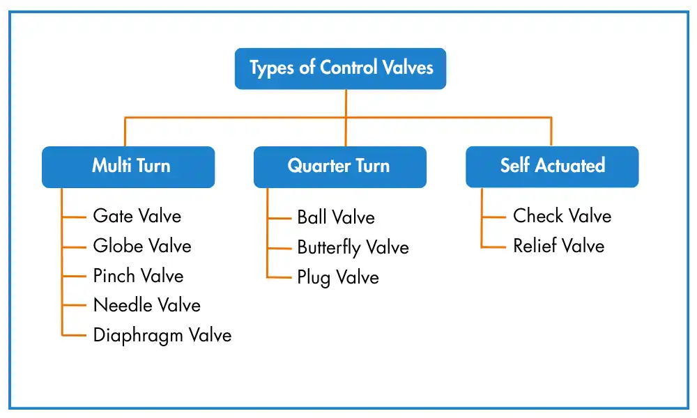
Common Types of Industrial Valves and Their Applications
Gate Valves
Gate valves are primarily used for on-off service. They offer very low flow resistance when fully open but are not suitable for throttling applications.Globe Valves
Globe valves provide excellent throttling characteristics and good shutoff capability. They are commonly used where flow regulation is required, even though they introduce higher pressure loss when fully open.Ball Valves
Ball valves provide quick quarter-turn operation and tight shutoff. They are ideal for isolation service but have poor throttling characteristics.Plug Valves
Plug valves are often used to divert or direct flow between multiple ports using a single valve body. They are suitable for on-off and limited throttling service.Butterfly Valves
Butterfly valves offer significant advantages in terms of weight, space, and cost, especially for large-diameter pipelines. They are commonly used in water, air, and low-pressure applications.Diaphragm Valves
Diaphragm valves are used where it is important to isolate the valve operating mechanism from the process fluid. They are common in corrosive, sanitary, and slurry applications.Pinch Valves
Pinch valves control flow by compressing a flexible tube. They are well suited for abrasive, viscous, or slurry services.Check Valves
Check valves automatically allow flow in one direction and prevent reverse flow. They operate without external control and protect equipment from backflow.Stop Check Valves
A stop check valve combines the features of a globe valve and a lift check valve. It allows flow in one direction while also providing manual shutoff capability.Safety and Relief Valves
Safety and relief valves protect systems from overpressure conditions. They automatically release excess pressure to prevent equipment damage or system failure.
What we learn today?
Valves are used in industrial systems to control fluid flow, pressure, and direction. Even though the purpose is similar, different valve types work in different ways and are selected based on process conditions and application needs.
Selecting the correct valve helps the system run smoothly and safely. Using an incorrect valve can lead to leakage, poor flow control, higher pressure loss, and increased maintenance. When the valve type matches the application, plant operation becomes more stable and reliable.
Understanding valve types, flow control methods, and basic construction helps engineers and technicians make correct decisions during design, operation, and maintenance.


I hope you like above blog. There is no cost associated in sharing the article in your social media. Thanks for Reading !! Happy Learning