Table of Contents
ToggleIntroduction: Why Choked Flow Matters in Control Valves
In any fluid system, proper valve sizing and correct flow characteristics are critical. When these are ignored, the system may enter a condition known as choked flow.
This condition can silently limit performance, reduce control accuracy, and in severe cases, damage the valve and downstream equipment.
Many engineers assume that increasing pressure difference across a control valve will always increase flow. In reality, this assumption fails once choked flow occurs.
At that point, no matter how much the downstream pressure is reduced, the flow rate simply refuses to increase.
Choked flow is not limited to a single medium.
Both gas and liquid control valves can experience this phenomenon under certain operating conditions. Understanding why it happens and how it behaves is essential for designing reliable and long-lasting process systems.
What Is Choked Flow in a Control Valve?
Choked flow is a flow condition in which the flow rate through a control valve becomes almost constant, even though the downstream pressure continues to drop.
Once choked flow occurs, reducing downstream pressure does not increase flow.
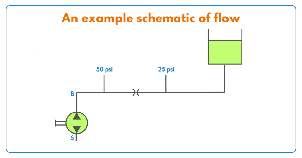
To understand this, consider a control valve installed in a pipeline:
When upstream pressure is higher and downstream pressure is lower, fluid naturally flows from high pressure to low pressure.
As the downstream pressure is reduced, the pressure drop across the valve increases.
Initially, this pressure drop increase causes the flow rate to rise.
However, beyond a certain limit, the flow reaches a maximum value.
After this point, further reduction in downstream pressure does not result in higher flow — the flow is said to be choked.
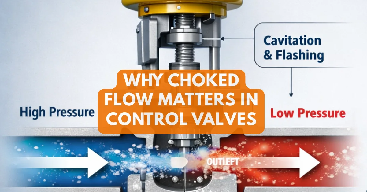
In liquid applications, choked flow commonly occurs due to cavitation or flashing inside the valve body. In gas applications, it occurs when the fluid velocity reaches sonic (critical) velocity at the valve’s vena contracta.
In both cases, the valve loses its ability to respond to pressure changes, and flow control becomes ineffective.

Under ideal conditions, the flow rate of a turbulent fluid through a control valve depends mainly on two factors:
1) The valve’s flow capacity (Cv) and
2) The pressure difference between the inlet and outlet (P1 − P2).
This relationship is defined by the basic control valve flow equation.

Where,
Q = Volumetric flow rate of liquid
Cv = Flow coefficient of valve
P1 = Upstream pressure of liquid
P2 = Downstream pressure of liquid
Gf = Specific gravity of liquid
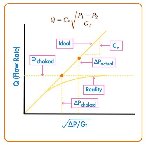
When the inlet pressure (P1) and the valve opening remain constant, the flow through a control valve normally increases as the downstream pressure (P2) is reduced.
Under ideal conditions, this behavior is predictable. Liquid flow increases in a near-linear manner when plotted against the square root of the pressure drop across the valve, corrected for the fluid’s specific gravity.
In real operating conditions, this increase does not continue indefinitely. Every control valve has a maximum flow limit. Once this limit is reached, the valve enters a choked flow condition. Beyond this point, the flow rate stops increasing, no matter how much the downstream pressure (P2) is further reduced.
The same principle applies to control valves handling gases. With constant inlet pressure (P1) and fixed flow area, gas flow initially increases as downstream pressure decreases.
But once critical conditions are reached, choking begins. After this point, the flow cannot increase further, regardless of how low the downstream pressure becomes.
Why Does Choked Flow Occur?
In liquid applications, choked flow occurs due to a sharp pressure drop inside the control valve. The valve inlet and outlet areas are much larger than the actual throttling region around the plug, seat, or cage. To maintain the same flow rate, liquid velocity increases significantly at this restricted section, known as the vena contracta.
According to Bernoulli’s principle, an increase in velocity causes a drop in pressure. As the liquid accelerates through the restriction, pressure falls sharply. When the fluid exits into the larger downstream piping, velocity decreases and part of the pressure is recovered. This pressure dip becomes more severe as flow increases.
If the pressure at the vena contracta drops below the liquid’s vapor pressure, vapor bubbles begin to form. These bubbles expand in volume and restrict flow. With further reduction in downstream pressure, vapor formation increases until the flow can no longer rise. This condition is known as choked flow.

In gas applications, flow velocity increases as downstream pressure decreases until it reaches sonic velocity. Beyond this point, flow cannot accelerate further due to the formation of a shock wave. Any additional reduction in downstream pressure has no effect on flow rate.
Choked gas flow commonly occurs in control valves, relief valves, vacuum systems, and high-velocity piping such as flare headers, where low pressure reduces the speed of sound and makes choking more likely.
Detecting Choked Flow in a Control Valve
Choked flow can often be identified through noise and vibration. Cavitation or high-velocity flow inside the valve may produce abnormal sound levels and noticeable pipe vibration, especially in liquid services.
The valve installation location can also be an indicator. If a valve is installed at a higher elevation than intended, the inlet pressure may drop below design values. This increases the pressure drop across the valve and can lead to cavitation and choked flow.
Another reliable method is flow and pressure comparison. Measure the actual flow or pressure drop across the valve and compare it with the expected flow calculated using the valve Cv. If the measured downstream flow is lower than the calculated value at the same Cv setting, the valve may be operating under choked conditions.

Most manufacturers provide maximum Cv values and choked pressure drop limits in their sizing data. If the actual pressure drop exceeds these limits, the valve cannot pass additional flow. Adjusting the valve Cv or increasing inlet pressure may be required.
The design stage is the best time to avoid choked flow. With known flow rates, pressures, and Cv values, engineers can evaluate pressure drop in advance and select a valve that operates safely without choking.
Resolving Choked Flow in Control Valves
Choked flow can be identified during design, commissioning, or even after years of operation. Regardless of when it is discovered, there are several practical ways to address the issue.
The simplest approach is to reduce the incoming flow. Lower flow reduces inlet pressure and, in turn, decreases the pressure drop across the valve. In many systems, this can be achieved by adjusting pump speed through a variable frequency drive (VFD) or other flow control settings.
Another option is to increase downstream pressure, provided the system design allows it. Raising downstream pressure reduces the pressure differential across the valve and helps move the valve out of the choked flow region.
If neither flow reduction nor pressure increase is possible, the remaining solution is to use a valve with a higher Cv value.
This usually requires replacing the existing valve, which can be challenging in operating plants. However, during the design phase, selecting a larger or different valve type is often the easiest and most effective fix.
Choked Flow in a Control Valve
The primary function of a control valve is to regulate flow within a process system. In practical terms, a control valve behaves like a variable orifice, continuously changing its opening to match the required flow rate.
Control valve manufacturers specify a minimum and maximum Cv for each valve. It is the designer’s responsibility to evaluate how the valve will perform at different Cv positions by calculating the expected pressure drop for the required flow and inlet pressure.
During valve selection, special attention must be given to low Cv operating conditions. At small openings, excessive pressure drop can occur, increasing the risk of cavitation and choked flow.
Designers should therefore verify that the selected valve will operate safely across its full range, even if the valve is incorrectly adjusted or installed.


I hope you like above blog. There is no cost associated in sharing the article in your social media. Thanks for Reading !! Happy Learning
2 Comments