Table of Contents
TogglePressure Sensing Lines (Impulse Lines) Introduction:
In industrial plants, pressure measurement looks simple from outside but in reality, the accuracy of pressure reading depends heavily on one hidden component: the pressure sensing line, also called the impulse line.
If these small pipelines are not designed or maintained properly, they can introduce serious measurement errors.
In this article, you will clearly understand:
1) What dynamic pressure really means
2) How dynamic pressure is measured
3) What pressure sensing (impulse) lines are
4) Common causes of pressure measurement errors
5) Practical solutions to impulse line problems
What Do We Mean by Dynamic Pressure?
Pressure is simply the force applied per unit area.
Mathematically:
Pressure (P) = Force (F) / Area (A)
P = F / A
However, in flowing fluids, pressure exists in two main forms:
1. Static Pressure
- This is the pressure when the fluid is not moving.
- It is measured at a point where flow velocity is zero.
- Most industrial pressure transmitters are calibrated for static pressure only.
2. Dynamic Pressure
- Dynamic pressure occurs due to the motion of the fluid.
- It is created by the collision of moving fluid molecules with a surface.
- The faster the fluid moves, the higher the dynamic pressure.
- It is especially important in flow measurement and aerodynamics.
Actual Pressure
The true pressure in a flowing system is the sum of both static and dynamic pressures:
Actual Pressure = Static Pressure + Dynamic Pressure
Dynamic pressure is widely used in:
- Aircraft airspeed measurement
- Turbo machinery
- Combustion systems
- Automotive testing
- Aerodynamic studies
What Are Pressure Sensing Lines (Impulse Lines)?
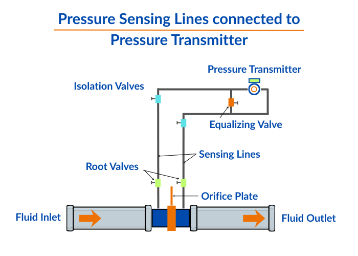
Pressure sensing lines, also known as impulse lines, are small pipes or tubes that connect the process pressure tapping point to the pressure transmitter.
Their main purpose is to:
- Safely transfer pressure from the process to the transmitter
- Protect the transmitter from high temperature, vibration, and corrosion
- Allow easy maintenance and replacement
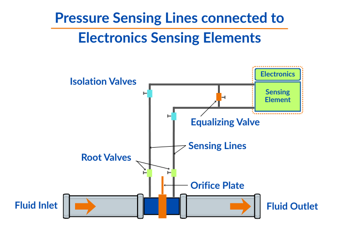
Figure 1 and Figure 2 show two typical impulse line arrangements used in industrial installations.
Why Are Pressure Transmitters Mounted Away from the Process?
Placing the transmitter directly on hot or vibrating pipelines can:
- Damage internal electronic components
- Reduce transmitter lifespan
- Increase maintenance cost
By using impulse lines and mounting transmitters at a safe distance:
- Temperature effects are minimized
- Vibration impact is reduced
- Maintenance becomes easier and safer
Types of Pressure Sensing Lines
Depending on the application, sensing lines may carry:
1. Liquid-Filled Impulse Lines
=> Filled with process liquid such as:
Oil
Water
Chemical solutions
=> Common in liquid pressure measurement
2. Gas-Filled Impulse Lines
=> Filled with:
Steam
Air
Nitrogen
=> Common in gas and steam applications
Special Cases
When the process medium must be isolated, devices such as:
Diaphragms
Bellows
Condensate pots
are used for medium separation.
Construction and Installation of Impulse Lines
Impulse lines are commonly manufactured from stainless steel, carbon steel, or copper tubing. The typical inner diameter ranges from 1.5 cm to 2.0 cm, while carbon steel tubing usually has a thickness of about 2 mm. To minimize leakage points, impulse lines are preferably installed as a single continuous length.
In most industrial plants, the average impulse line length is 40 to 50 meters, although in special applications it may extend up to 300 meters.
Proper Slope Requirement
For reliable operation, liquid impulse lines must slope downward toward the process, while gas impulse lines must slope upward. A standard slope of 10 cm per meter is generally recommended.
If proper sloping is not possible, a high-point vent is required for liquid lines, and a low-point drain is required for gas lines. This arrangement ensures self-venting of trapped air and proper draining of condensate.
You can check my article: 7 Engineering Benefits of Impulse Line Installation in a Sloping Manner
Causes of Errors in Pressure Measurement
Impulse line problems are among the largest hidden sources of pressure measurement errors in industrial plants. The most common causes are described below.
1. Voids (Trapped Air or Gas)
When air or gas becomes trapped inside a liquid-filled impulse line, it leads to false pressure readings and slow transmitter response. In differential pressure (DP) measurement, trapped air on the low-pressure side results in a higher than actual DP reading.
2. Blockages
Blockages are typically caused by chemical deposits, mud or slurry solidification, dirt, corrosion products, improper valve alignment, or bent tubing. A blocked impulse line causes slow response, incorrect pressure indication, and in extreme cases, complete signal loss.
3. Leakage
Leakage may develop at root valves, isolation valves, equalizing valves, tube fittings, or high-pressure joints. This leads to a pressure drop in the impulse line, unstable transmitter readings, and false low-pressure indication.
4. Freezing
In cold weather, impulse lines can freeze internally, preventing proper pressure transmission. The transmitter may then show a constant reading or no response to process changes. The most common reason for this problem is damaged or failed heat tracing.
Pressure Sensing Line Problem Solving – Best Practices
To maintain accurate and reliable pressure measurement, the following best practices should be followed in all industrial installations.
1. Periodic Blowdown and Flushing
Regular blowdown and flushing of impulse lines help remove air pockets, dirt, and chemical deposits. This practice is especially critical in differential pressure (DP) measurements and dirty or slurry service applications, where blockage risk is high.
2. Noise Analysis Technique
Noise analysis is used to detect voids, blockages, and leaks in impulse lines by evaluating the dynamic response of the sensing system. Its key advantage is that it automatically considers the actual length, diameter, and internal condition of the impulse line, providing a true picture of real-world performance.
3. Heat Tracing and Insulation
Heat tracing and proper insulation prevent freezing of impulse lines in cold environments. Regular inspection of heating cables and insulation condition is necessary to ensure continuous protection.
4. Proper Valve Operation
Always ensure the correct opening sequence of isolation and equalizing valves, and avoid partial valve closures, as these can cause false pressure readings and unstable transmitter output.
What we learn today?
Pressure sensing lines, also known as impulse lines are used to transfer accurate process pressure to transmitters. However, issues such as voids, blockages, leakage, and freezing can silently introduce serious measurement errors and slow response time.
Proper design, correct sloping, regular flushing, effective heat tracing, and correct valve operation are essential to keep impulse lines healthy.
By following good installation and maintenance practices, industries can ensure reliable pressure measurement, stable process control, and longer instrument life.


I hope you like above blog. There is no cost associated in sharing the article in your social media. Thanks for Reading !! Happy Learning