Table of Contents
ToggleIn any modern process plant whether it is oil & gas, chemical, power, water treatment, or pharma, control valves quietly do one of the most important jobs: they regulate flow.
But what actually ensures that a control valve opens exactly to 35%, 62%, or 90% when the controller demands it?
The answer is the control valve positioner.
Many people think a positioner is just a signal converter, but in reality, it is a highly precise closed-loop servo control system mounted directly on the valve.
Let’s understand how it really works step by step in a simple and practical way.
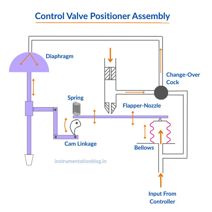
Control Valve Positioner Assembly
A valve positioner works using a high-gain amplifier, which may be pneumatic or electro-pneumatic, along with a feedback mechanism that continuously senses the actual valve position.
When the controller sends a signal indicating that the valve should close, the input pressure to the bellows decreases. This causes the flapper to move away from the nozzle, reducing the pressure downstream of the orifice. As a result, the pressure acting on the diaphragm drops and the valve starts to close.
As the valve moves, the feedback arm shifts upward and rotates the cam in a clockwise direction. This motion lifts the beam, increasing the back pressure at the nozzle until a new balance (equilibrium) is reached. The changeover cock allows the controller signal to be applied directly to the diaphragm when required.
Please refer image below.
1. What Is a Control Valve Positioner?
A control valve positioner is a device that:
- Receives a control signal from the PLC or DCS
- Converts that signal into pneumatic pressure
- Moves the valve stem to the exact required position
- Continuously corrects the position using feedback
In simple words:
The controller decides the position, but the positioner makes sure the valve actually reaches and holds that position accurately.
2. Signal from the Controller (4–20 mA)
Everything starts in the control room.
The DCS or PLC sends a 4–20 mA control signal to the positioner. This current represents the required valve opening:
- Low current = valve more closed
- High current = valve more open
In most modern positioners, this same 4–20 mA loop also powers the positioner electronics (2-wire loop-powered devices).
This signal is called the setpoint which is the desired valve position.
3. I/P Conversion – From Electrical to Pneumatic
Valves and actuators do not understand electric current. They work on air pressure. So the next job of the positioner is to convert the electrical signal into a pneumatic signal.
This is done using an I/P (Current to Pressure) converter inside the positioner.
Depending on the design, this conversion is done using:
- Flapper and nozzle system
- Piezoelectric micro-valves
- Torque motor with force balance principle
The standard output after this conversion is:
3–15 psi pneumatic signal corresponding to 4–20 mA
This is the most widely used industrial pneumatic control range.
4. Pneumatic Relay – Pressure Amplification
The 3–15 psi signal is too weak to move large industrial actuators directly. So the positioner uses an internal pneumatic relay or booster.
This relay:
- Takes the low control pressure
- Amplifies it to high actuator pressure (typically 20–80 psi)
- Supplies enough air volume for fast and stable valve movement
This is what gives control valves:
- Fast response
- Strong shut-off force
- Stable positioning even at high pressure drops
5. Actuator Motion – Converting Air to Movement
Now the amplified air pressure enters the actuator.
The actuator converts pneumatic energy into mechanical motion using mechanisms like:
- Diaphragm and spring
- Piston and cylinder
- Rack-and-pinion
- Scotch yoke (for high torque)
This mechanical movement:
- Pushes or pulls the valve stem
- Rotates the valve shaft
- Opens or closes the valve to the required position
6. Position Feedback – The Heart of Closed-Loop Control
This is what truly makes a positioner intelligent.
A feedback sensor continuously measures the actual valve position and sends this information back to the positioner electronics.
Common feedback technologies include:
=> Mechanical linkage
=> Potentiometer
=> Magnetic position sensor
=> Hall-effect sensor
=> Optical encoder
The positioner constantly compares:
- Commanded position (from 4–20 mA)
- Actual stem position (from feedback sensor)
If there is any error, it automatically adds or releases air pressure to correct the position.
This happens continuously and extremely fast, forming a closed-loop servo control system, similar to a small PID controller installed directly on the valve.
7. Example of Signal Conversion
Let’s see a simple real-world example:
| Control Signal | Pneumatic Output | Valve Position |
|---|---|---|
| 4 mA | 3 psi | 0% Open |
| 12 mA | 9 psi | 50% Open |
| 20 mA | 15 psi | 100% Open |
If the valve is commanded to 50% but friction allows it to reach only 45%, the positioner automatically corrects this error by increasing pressure until 50% is achieved.
8. Why a Positioner Is So Important (Even When a Valve Can Work Without It)
Technically, a control valve can operate without a positioner—but in real industrial conditions, that comes with many problems:
=> Poor positioning accuracy
=> Slow response time
=> Large deadband and hysteresis
=> Unstable control during pressure fluctuations
=> High process variability
A positioner completely eliminates these issues by maintaining precise and repeatable valve travel, regardless of process disturbances.
9. Advanced Functions in Modern Digital Valve Positioners
Today’s digital valve positioners are no longer simple I/P converters. They are smart field devices with powerful diagnostic and predictive maintenance features:
Auto-stroking and Adaptive Tuning
Automatically calibrates valve travel and optimizes response to reduce:
- Hysteresis
- Deadband
- Overshoot
Friction and Stiction Detection
Identifies:
- Packing wear
- Stem binding
- Actuator mechanical resistance
Valve Signature & Step-Response Curves
Records:
- Valve travel vs. pressure
- Dynamic response curves
Partial Stroke Testing (PST)
Critical for ESD and safety valves, allowing:
- Online safety testing without shutting down the process
- Compliance with SIL requirements
Air Consumption Optimization
Reduces unnecessary bleeding and:
- Lowers compressor load
- Saves energy
- Improves plant efficiency
Self-Diagnostics
Continuously monitors:
- Supply air pressure
- I/P drift
- Travel deviation
- Feedback sensor failure
10. Role of Positioners in Safety Instrumented Systems (SIS)
When used with safety-critical control and shutdown valves, modern digital positioners:
- Support SIL (Safety Integrity Level) compliance
- Meet IEC 61511 standards
- Enable proof testing and online diagnostics
- Improve functional safety reliability
This makes positioners a key part of plant safety, not just control accuracy.
What we learn today?
A control valve positioner is not just a signal converter. It is a closed-loop electropneumatic servo control system that:
- Converts 4–20 mA into precise pneumatic pressure
- Amplifies air for strong actuator movement
- Continuously monitors actual valve position
- Automatically corrects any positioning error
- Improves control accuracy, stability, and reliability
- Enables predictive maintenance and safety compliance
In modern plants, smart digital positioners play a critical role in:
- Reducing process variability
- Preventing valve failures
- Saving energy
- Ensuring process safety


I hope you like above blog. There is no cost associated in sharing the article in your social media. Thanks for Reading !! Happy Learning