Table of Contents
ToggleTemperature and Pressure Compensation: Introduction
Temperatureand pressure compensation is a measurement technique used in industrial instruments to correct readings to standard reference conditions, typically 25°C temperature and 1 standard atmosphere pressure.
Since most process measurements are taken under varying operating conditions, direct readings can differ from one location or time to another.
To solve this, instruments measure the actual on-site temperature and pressure and apply a compensation formula to convert the measured values to standard conditions.
This ensures that readings remain accurate, comparable, and consistent across different processes, installations, and operating environments, making data analysis and reporting much more reliable.
Types of Instruments Requiring Temperature and Pressure Compensation
Many industrial flow instruments operate under changing process conditions, where temperature and pressure are rarely constant.
In such cases, compensation becomes essential to ensure accurate and comparable measurements. Instruments that commonly require temperature and pressure compensation include the following.
1 Vortex Flow Meters
Vortex flow meters are widely used for measuring gases, saturated steam, superheated steam, and liquids. These instruments detect the frequency of vortices generated downstream of a bluff body and relate it to flow velocity.
Temperature and pressure compensation is required in vortex flow meters mainly because of density variation. As operating conditions change, fluid density changes accordingly, which directly impacts the calculated flow value.
In practical installations, compensation is achieved by:
Measuring process temperature using a built-in RTD or temperature probe.
Measuring line pressure using an external pressure transmitter.
Using these inputs to calculate mass flow or standard volumetric flow.
This compensated measurement approach is commonly used in compressed air systems, steam distribution lines, and industrial gas applications, where operating conditions fluctuate throughout the day.
2 Differential Pressure Flow Meters
Differential pressure flow meters measure flow by creating a pressure drop across a primary element such as an orifice plate, Venturi tube, or Annubar sensor. The differential pressure generated is proportional to the square of the flow velocity.
However, DP flow meters inherently measure actual volumetric flow, not mass flow or standard flow. This creates a need for temperature and pressure compensation, especially in gas and steam applications.
Compensation is required because:
Gas and steam density changes with pressure and temperature.
The same volumetric flow can represent different mass flow values under different conditions.
Standardized flow values are required for reporting and billing.
In most installations, temperature and pressure signals are fed into a flow computer or smart transmitter, which performs real-time compensation calculations.
3 Gas Turbine Flow Meters
Gas turbine flow meters operate by converting the kinetic energy of flowing gas into rotational motion of a turbine. The rotational speed is directly related to the volumetric flow rate at line conditions.
Since gas density is highly sensitive to operating conditions, compensation becomes essential when turbine meters are used for critical applications. Without compensation, the same flow rate can appear different when temperature or pressure changes.
Temperature and pressure compensation enables:
Conversion of line volume flow into standard volume flow.
Accurate mass flow calculation for process control.
Consistent readings for custody transfer or energy monitoring.
This makes compensated turbine meters suitable for natural gas, fuel gas, and clean industrial gas measurements.
4 Flow Totalizers
Flow totalizers are dedicated devices designed to calculate and accumulate compensated flow values over time. These instruments are commonly used where total consumption data is more important than instantaneous flow rate.
A typical flow totalizer works by:
Receiving flow signals in the form of current, voltage, or pulse inputs.
Accepting temperature and pressure signals from field transmitters.
Applying compensation algorithms to calculate standardized flow totals.
Flow totalizers are widely used for superheated steam, saturated steam, and general gas flow applications, particularly in energy management and utility monitoring systems.
Methods of Temperature and Pressure Compensation
Temperature and pressure compensation methods depend mainly on the type of fluid being measured and the required accuracy. In industrial instruments, compensation is broadly implemented using gas laws, steam property data, or intelligent digital algorithms.
1 General Gas Compensation
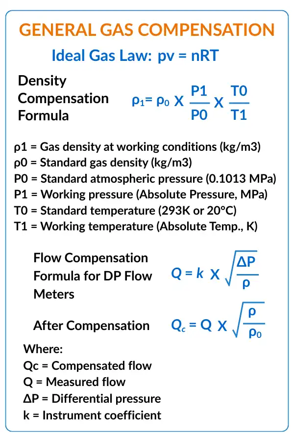
For most industrial gas applications, temperature and pressure compensation is based on the Ideal Gas Law, which explains the relationship between pressure, volume, and temperature:
P × V = n × R × T
This equation forms the foundation for gas density correction. Since gas density changes directly with pressure and inversely with temperature, compensation is applied by correcting the gas density from working conditions to standard conditions.
The commonly used density compensation formula is:
ρ₁ = ρ₀ × (P₁ / P₀) × (T₀ / T₁)
Where:
ρ₁ = Gas density at working conditions (kg/m³)
ρ₀ = Gas density at standard conditions (kg/m³)
P₀ = Standard atmospheric pressure (0.1013 MPa)
P₁ = Working pressure (absolute pressure, MPa)
T₀ = Standard temperature (293 K or 20°C)
T₁ = Working temperature (absolute temperature, K)
This compensation approach is widely used because:
Most industrial gases closely follow ideal gas behavior.
The formula is simple and easy to implement in transmitters and flow computers.
It provides sufficiently accurate results for compressed air and general gas applications.
Flow Compensation in Differential Pressure Flow Meters
Differential pressure flow meters measure flow using the pressure drop across a primary element. The basic flow equation is:
Q = k × √(ΔP / ρ)
Where:
Q = Measured flow
ΔP = Differential pressure
ρ = Gas density
k = Instrument coefficient
Since density changes with temperature and pressure, the measured flow must be corrected. After compensation, the corrected flow is calculated as:
Qᶜ = Q × (ρ / ρ₀)
Where:
Qᶜ = Compensated flow
ρ = Actual gas density
ρ₀ = Standard gas density
This method ensures that:
Flow values are converted from actual conditions to standard conditions.
Measurements remain comparable across different operating pressures and temperatures.
Reporting in Nm³/h or Sm³/h becomes accurate and consistent.
2 Steam Compensation
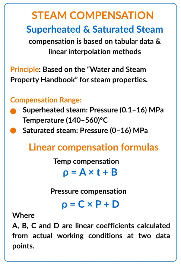
Steam compensation is more complex than gas compensation because steam does not follow the ideal gas law, especially near saturation conditions. Therefore, steam compensation relies on tabular data and interpolation methods derived from standard steam property references.
The compensation principle is based on data from the Water and Steam Property Handbook, which provides accurate values of density, enthalpy, and other properties across a wide range of pressures and temperatures.
Typical compensation ranges include:
Superheated steam with pressure from 0.1 to 16 MPa (gauge) and temperature from 140°C to 560°C.
Saturated steam with pressure from 0 to 16 MPa (gauge).
To simplify calculations inside instruments, linear interpolation methods are often used between two known data points.
Linear temperature compensation is expressed as:
ρ = A × t + B
Linear pressure compensation is expressed as:
ρ = C × P + D
Where:
A, B, C, and D are linear coefficients calculated using two known operating points from steam tables.
This method allows instruments to:
Achieve acceptable accuracy without storing large steam tables.
Perform real-time compensation for both saturated and superheated steam.
Maintain stable measurement performance in steam energy applications.
3 Intelligent Compensation Methods
Modern digital instruments use intelligent compensation techniques that go beyond simple linear correction. These methods are implemented using internal microprocessors and advanced algorithms.
The working principle involves multi-point linearization, where the flow signal is corrected at multiple points across the operating range rather than at just one or two points.
This approach offers several advantages:
High accuracy across the entire measuring range, not just at nominal flow.
Improved range ratio, often up to 1:15, compared to the typical 1:5 range ratio of standard vortex flow meters.
Better performance under fluctuating pressure and temperature conditions.
Intelligent compensation methods are commonly used in smart vortex meters, flow computers, and advanced transmitters, especially where precision measurement and energy accounting are critical.
Application Examples
Understanding formulas is important, but temperature and pressure compensation becomes much clearer when seen in real industrial applications. The following examples show how compensation is applied in day-to-day measurement systems.
1 Superheated Steam Flow Measurement in a Power Plant
In power plants, superheated steam flow measurement is critical for energy balance, efficiency monitoring, and turbine protection. Since steam properties change significantly with temperature and pressure, compensation is mandatory.
Design Conditions
The system operates under the following conditions:
Steam temperature of 250°C.
Operating pressure of 1.2 MPa (gauge).
Differential pressure range from 0 to 30 kPa.
Flow range from 0 to 40 t/h.
Instrument Configuration
To achieve accurate compensated flow measurement, the instrumentation system is configured as follows.
Temperature Channel
The temperature is measured using a resistance temperature detector (RTD) with the output expressed in degrees Celsius. This signal is used directly for compensation, without square-root extraction or additional correction at the transmitter level.Pressure Channel
Pressure is measured using a standard 4–20 mA pressure transmitter, with the pressure value expressed in MPa. Similar to the temperature signal, this channel does not require square-rooting or local compensation.Flow Channel
Flow is derived from the differential pressure transmitter output (4–20 mA). The flow range is configured from 0 to 40 t/h, with totalization enabled. Compensation is set specifically for superheated steam, allowing the system to calculate accurate mass flow based on real-time temperature and pressure inputs.
With this configuration, the flow computer or smart transmitter continuously calculates compensated steam flow, ensuring reliable data for plant operation and performance analysis.
2 Air Flow Measurement Calculation
Air flow measurement is a common requirement in compressed air systems, ventilation networks, and industrial utilities. Since air density changes with temperature and pressure, compensation is required to convert measured volume into standard mass or standard volume.
To calculate the standard air mass, the following equation is used:
m = (M × P × V) / (R × T)
Where:
M = Air molar mass (29 g/mol)
P = Standard atmospheric pressure (101325 Pa)
V = Volume (1 m³)
R = Gas constant (8.314 J/(mol·K))
T = Standard temperature (293.15 K)
Using these values, the calculated mass of air is approximately:
m ≈ 1.2 kg
This means that under standard conditions, 1 m³ of air has a mass of about 1.2 kg.
When operating conditions change, density must be recalculated. For example, if the system operates at higher pressure and temperature, the compensated air density becomes:
ρ₁ = 1.2 × (0.15 / 0.1013) × (293.15 / 323.15) ≈ 1.61 kg/m³
This calculation shows that:
Increased pressure raises air density.
Increased temperature reduces air density.
The combined effect determines the final compensated density.
Based on this density change, the measured air flow must be compensated to ensure accurate mass flow or standard volume reporting. Without this correction, flow values would be misleading and unsuitable for performance analysis or energy accounting.
Advantages of Temperature and Pressure Compensation
Improved Measurement Accuracy
Temperature and pressure compensation corrects density changes caused by operating condition variations, ensuring accurate gas and steam flow measurements under all process conditions.Unified Comparison Standard
By converting measurements to standard conditions, compensated values can be easily compared across different systems, locations, and time periods.Extended Flow Measurement Range
Intelligent compensation techniques can increase the range ratio up to 1:15, which is significantly higher than the typical 1:5 range of conventional instruments.Improved Fault Diagnosis
Continuous monitoring of temperature and pressure signals enables early fault detection, improving measurement reliability and system uptime.
Considerations
When applying temperature and pressure compensation, it is important to understand where it is most effective, its limitations, and basic installation requirements.
1 Suitable Applications
Temperature and pressure compensation is best suited for applications where operating conditions are stable or moderately varying. Typical examples include:
Compressed air measurement, where density variation significantly affects flow readings.
Internal measurement scenarios, such as plant utilities or energy monitoring, where standardized reporting is required.
Applications with limited accuracy requirements, where simplified compensation methods are sufficient.
2 Limitations
Despite its benefits, temperature and pressure compensation has certain limitations:
Higher maintenance costs due to additional temperature and pressure sensors.
In some systems, data retrieval is limited to the flow meter or totalizer display, making integration more complex.
Suspended pipeline installations are generally unsuitable due to mechanical and signal stability concerns.
3 Installation Requirements
Correct installation is essential for reliable compensation:
Temperature and pressure measurement points should be installed as close as possible to the flow measurement point.
All measurement signals must be properly synchronized to ensure accurate real-time compensation


I hope you like above blog. There is no cost associated in sharing the article in your social media. Thanks for Reading !! Happy Learning