Table of Contents
ToggleSplit Range Control: Introduction
In many industrial processes, we need to control one important process variable (like temperature, pressure, or level) using more than one final control element. For example:
1) To control temperature, we may use a heating steam valve & a cooling water valve
2) To control tank level, we may use two different outlet valves
3) To control pressure, we may use a vent valve & a supply valve
But how does the controller decide which valve to open and when?
That is where Split Range Control is used.
Split range control is a technique used in process control where one controller output signal is split into two (or more) different control outputs.
Each output operates a different valve or device over a specific portion of the signal range.
Example:
Controller output 4–12 mA → Valve A
Controller output 12–20 mA → Valve B
Easy, right? Let us learn in detail.
What is Split Range Control?
Definition:
Split range control is a control strategy where a single controller manipulates multiple control elements, each handling a part of the controller’s output span.
The output of a standard controller is usually 4–20 mA (or 0–100%). In split range:
1) The first valve gets control action from 4–12 mA
2) The second valve gets control action from 12–20 mA
This “splitting” helps the process react properly under different load or conditions.
Why Do We Use Split Range Control?
Because one control element cannot always handle the entire job.
Typical reasons:
1) Single valve cannot provide full control range
2) Need for heating + cooling
3) Need for pressure supply + venting
4) Handling two different flow sources
5) Improving energy efficiency
6) Maintaining process stability under varying conditions
It helps to keep the process variable within limits while choosing the most suitable actuator at any moment.
Example: Split Range for Temperature Control Application
It becomes much easier to understand split-range control when we look at a real example like temperature control in a process system.
In this case, the product might sometimes need heating and at other times cooling, depending on its temperature.
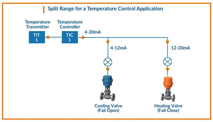
The illustration below shows how the temperature transmitter, the controller, and the two control valves are arranged in a split-range temperature control setup.
Here, the controller’s output signal (0%–100%) is divided into two separate operating ranges — one for each valve:
- When the controller output is 0% to 50%, the cooling valve is active.
- It is fully open at 0% and closes gradually until it is fully shut at 50%.
- When the controller output is 50% to 100%, the heating valve takes control.
- It begins to open at 50% and becomes fully open at 100%.
So the controller decides whether heating or cooling is required, simply based on where its output falls in the split range.
There are multiple ways to configure the valves in a split-range setup so that each responds to a different part of the signal.
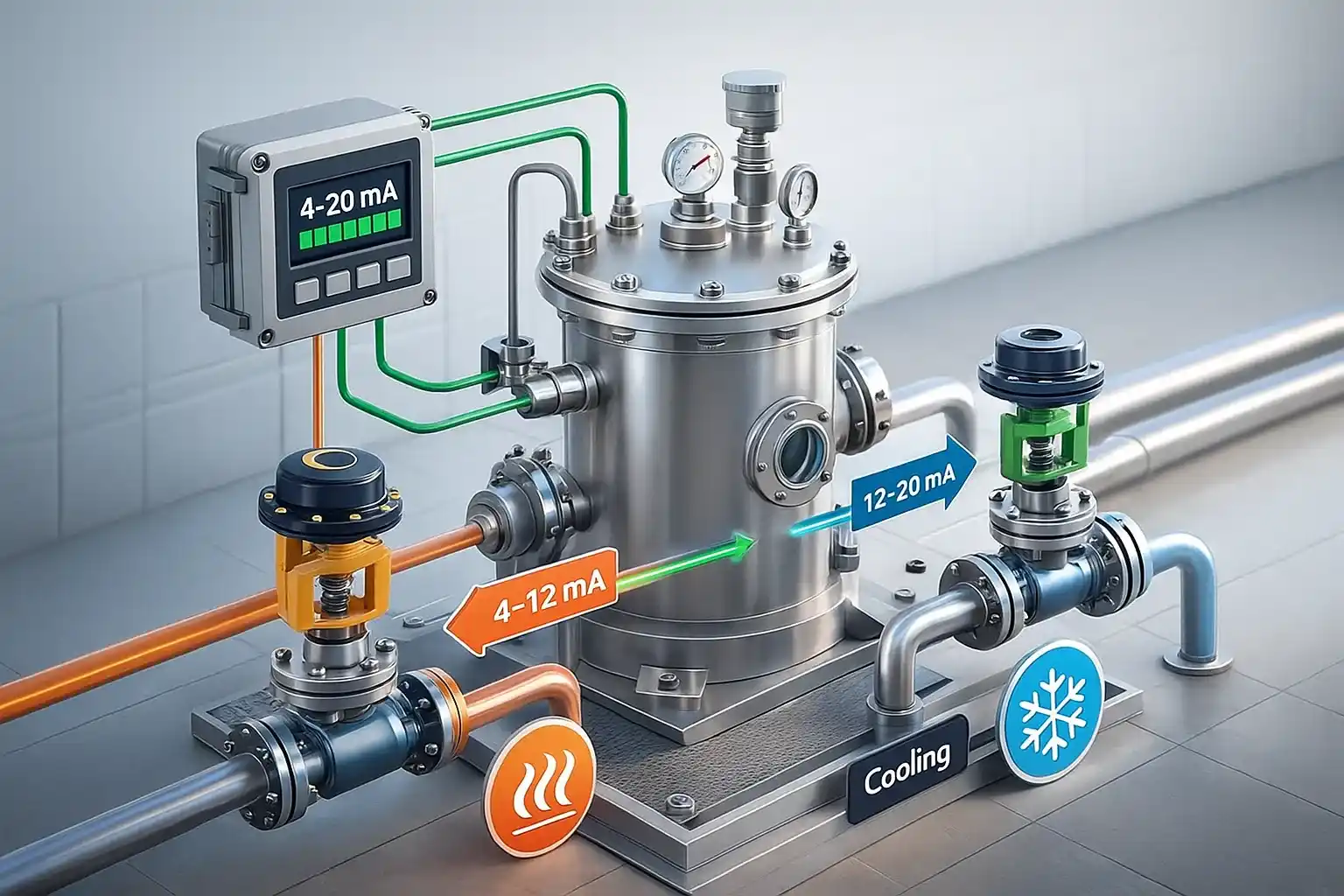
In this example, two I/P (current-to-pressure) converters are used to divide the output:
- First converts 4–12 mA → Cooling valve
- Second converts 12–20 mA → Heating valve
The best part is that with this wiring method, we don’t need a special controller — a standard output signal works perfectly for split-range control.
Example: Temperature Control With Heating & Cooling
Imagine a reactor that always needs to stay at 70°C:
1) Temperature drops → We add steam (heating)
2) Temperature rises → We add cooling water
One PID controller measures temperature and gives output (4–20 mA).
How does it work?
| Output Signal | Action | Device |
|---|---|---|
| 4–12 mA | Steam valve opens (heat increases) | Heating |
| 12–20 mA | Cooling valve opens (heat decreases) | Cooling |
1) If temperature is low → controller goes toward 4 mA → steam opens
2) If temperature is high → controller goes toward 20 mA → cooling opens
At the middle point (~12 mA), both may remain closed — perfect temperature!
Types of Split Range Control
There are mainly three types:
1) Fully Sequential Split Range
- First valve works → then stops
- Second valve works after first reaches full stroke
Example:
Valve A: 4–12 mA
Valve B: 12–20 mA
No overlap.
2) Fully Overlapping Split Range
- Both valves work in the middle range
- Helps prevent sudden transitions
Example:
Valve A: 4–16 mA
Valve B: 8–20 mA
Overlap: 8–16 mA (smooth handover)
3) Complementary Split Range
- One valve closes as the other opens
- Ideal for systems like supply vs. vent
Example for pressure control:
Valve A (supply): 4–20 mA open → 20–4 mA close
Valve B (vent): 4–20 mA close → 20–4 mA open
Used when both valves shouldn’t be open together.
How the Output Signal is Assigned
It depends on:
1) Type of valves (air-to-open / air-to-close)
2) Fail-safe requirements
3) Process logic
The output assignment is done using:
- Current splitters
- Positioners with split configuration
- Control system logic (DCS/PLC)
Control Valve Actions in Split Range
Two common valve types:
| Valve Action | Meaning | Fail Position |
|---|---|---|
| Air-to-Close (ATC) | More air → closes | Fails open |
| Air-to-Open (ATO) | More air → opens | Fails closed |
So when designing split range:
1) Engineers ensure safety first
2) Heating valve may be made fail-close
3) Cooling valve may be fail-open (safety cooling)
Where is Split Range Control Used?
Here are simple and real process areas:
| Controlled Variable | Valve Functions |
|---|---|
| Temperature | Steam valve (heat) + Cooling water valve |
| Pressure | Supply valve + Vent valve |
| Level | Two outlet valves to different locations |
| Flow | Two different gas streams |
| Composition | Control of multiple reagent inlets |
Industries using it:
- Chemical reactors
- Oil & Gas facilities
- Power plants
- Food & beverage
- Water treatment plants
Basically, wherever precise process control is needed
Practical Setup and Tuning Tips
| Item | Recommendation |
|---|---|
| Tuning | Slow transitions → Avoid cycling |
| Overlap | Use for smooth handover |
| Calibration | Ensure valves respond correctly in assigned ranges |
| Safety | Fail-safe direction must support process safety |
| Hysteresis | Choose valves with low friction & good actuator performance |
Also, ensure position feedback is correctly configured.
Common Problems & How to Avoid Them
| Problem | Cause | Solution |
|---|---|---|
| Process swings near split point | Poor tuning / no overlap | Add small overlap, retune |
| Both valves fight each other | Wrong range mapping | Verify DCS config |
| Delayed response | Sticky valves / hysteresis | Valve maintenance |
| Wrong fail position | Incorrect design | Update safety logic |
Testing before commissioning is very important!
Very Simple Example
Think of an AC room:
- When room is very cold → heater turns ON
- When room is very hot → AC turns ON
- When perfect → Both OFF
Your body (controller) senses temperature and decides action
Two devices (heater & AC) operate in different ranges
This is exactly like split range control in industry
Split range control is simple yet powerful.
✔ One controller → Multiple controlled devices
✔ Output signal split into different operating ranges
✔ Used where one valve cannot handle full control requirements
✔ Very useful for heating/cooling and pressure control
✔ Requires careful tuning, configuration & safety planning
In short:
Split range control helps keep processes stable across wide conditions using multiple control elements — smart and efficient!


I hope you like above blog. There is no cost associated in sharing the article in your social media. Thanks for Reading !! Happy Learning