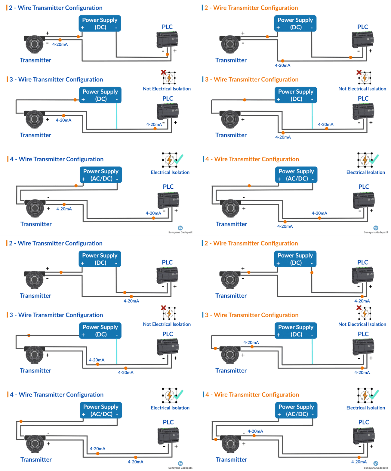
2-Wire 3-Wire 4-Wire Transmitters in Industrial Automation is a basic concept but many engineers get confused about the wiring.
4 to 20 mA transmitters are everywhere!
They are used to measure and send signals for temperature, pressure, level, and many other process parameters to controllers like PLCs.
But here is where many engineers and technicians get stuck: WIRING CONFIGURATIONS!
Table of Contents
ToggleA transmitter takes a signal from a sensor (like temperature or pressure) and converts it into a standard control signal most commonly 4 to 20 mA.
4 mA = Minimum value
20 mA = Maximum value
Now, let us talk about how these transmitters are wired and connected to a PLC (Programmable Logic Controller).
👉 Uses just two wires: one for power and one for signal, same line does both jobs.
👉 Powered by 24V DC.
👉 The current flows in a loop from power supply ➝ transmitter ➝ PLC ➝ back to supply.
Pros:
✔ Simple & cost-effective
✔ Low maintenance
✔ Saves wiring effort
Cons:
✘ Less accurate
✘ Can’t go below 4 mA even if there’s a fault – can’t detect zero-current faults.

👉 Uses separate wires for power and signal.
👉 Shares a common ground between the power supply and signal return.
Pros:
✔ Requires only 3 wires
✔ Same power source used for both transmitter & PLC
Cons:
✘ No electrical isolation
✘ Can be affected by interference
✘ Tricky wiring for beginners
👉 Has two pairs: one for power, one for signal
👉 Can be powered by AC or DC
👉 Signal wiring is fully isolated from power
Pros:
✔ High accuracy & stable signals
✔ Excellent electrical isolation
✔ Easy for technicians to wire
✔ Fewer false alarms
Cons:
✘ Higher cost
✘ Not ideal for hazardous areas due to risk of ignition if powered by high voltage
Understanding how to wire these transmitters correctly ensures safe, accurate & reliable measurement in your automation systems.

I hope you like above blog. There is no cost associated in sharing the article in your social media. Thanks for reading!! Happy Learning!!