
Table of Contents
ToggleIn modern process industries, smart transmitters have replaced traditional analog transmitters because of their better accuracy, digital intelligence, and communication capabilities.
However, with this advancement, calibration has also become more detailed.
One of the most misunderstood topics in smart transmitter calibration is Sensor Trim and Output Trim.
Many technicians assume that once the LRV and URV values are entered, the transmitter is fully calibrated.
In reality, this is only range configuration, not true calibration. Without proper sensor trim and output trim, measurement errors can still exist even when the transmitter appears correctly ranged.
Let us understand the terms sensor trim and output trim.
From Conventional Transmitters to Smart Transmitters
In older analog transmitters, calibration was simple.
Only two physical adjustments existed: zero and span.
Applying 0% input and adjusting zero, followed by 100% input and adjusting span, was sufficient. There were no digital conversions or internal processing.
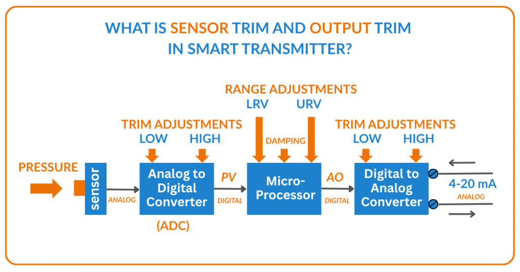
A smart transmitter works in a completely different way. The process signal is first converted into a digital value, processed inside a microprocessor, and then converted back into an analog 4–20 mA signal. Internally, the signal path looks like this:
- Sensor
- Analog-to-Digital Converter (ADC)
- Microprocessor
- Digital-to-Analog Converter (DAC)
- 4–20 mA Output
Because of this digital conversion inside the transmitter, two different calibrations are required:
- Sensor Trim → for ADC accuracy
- Output Trim → for DAC accuracy
What Is Sensor Trim?
Sensor trim is the calibration of the transmitter’s input measurement system. It corrects the accuracy of the ADC, which converts the sensor’s electrical signal into a digital value for the microprocessor.
Over time, due to temperature variation, aging, mechanical stress, and electronic drift, the ADC can shift slightly. When this happens, the transmitter may interpret the actual process value incorrectly. Even a small ADC error will affect every output value generated by the transmitter.
In simple words:
- Sensor trim ensures that the transmitter’s measured digital value exactly matches the true applied process value.
- Sensor trim corrects measurement accuracy, not output scaling.
This is why sensor trim is the foundation of accurate calibration.
What Is Output Trim?
Output trim is the calibration of the transmitter’s output signal circuit. It corrects the DAC, which converts the microprocessor’s digital calculation into a physical 4–20 mA signal.
Even when the internal calculation is correct, the output current can still be wrong due to DAC drift. For example, the transmitter may calculate exactly 4.00 mA but physically output 4.10 mA. This creates control and indication errors at the DCS or PLC.
In simple terms:
- Output trim ensures that the calculated digital value is converted into an exact real current signal.
- Output trim corrects signal transmission accuracy.
Why Setting LRV and URV Alone Is Not Enough
Setting the Lower Range Value (LRV) and Upper Range Value (URV) only tells the transmitter how to scale the measured value between 4 mA and 20 mA. It does not correct internal electronic errors.
To understand this clearly, consider this situation:
- LRV and URV are configured correctly
- DAC is perfectly trimmed
- ADC has developed a small zero drift
Now, when zero pressure is applied, the ADC sends a slightly incorrect digital value to the microprocessor.
The microprocessor calculates the output based on this wrong input, and the DAC faithfully converts it into a current signal. The result is an incorrect 4–20 mA output even though the range is correctly configured.
This proves a critical point:
Encoding LRV and URV into the microprocessor does not guarantee true accuracy unless sensor trim is also performed.
Correct Calibration Sequence for Smart Transmitters
For true calibration, the order of steps is extremely important. The correct sequence is:
Perform Sensor Trim first to correct the input measurement.
Set the LRV and URV according to the required process range.
Perform Output Trim to correct the 4–20 mA output signal.
Skipping any of these steps can introduce hidden measurement errors, even if the transmitter appears to be functioning normally.
Difference Between Sensor Trim and Output Trim (Quick View)
- Sensor Trim corrects how accurately the transmitter measures the physical process.
- Output Trim corrects how accurately the transmitter sends the 4–20 mA signal.
- Sensor trim adjusts the ADC.
- Output trim adjusts the DAC.
- Both trims are equally important and serve different internal functions.
What we learn today?
Sensor Trim and Output Trim are not optional in smart transmitter calibration. Setting LRV and URV only defines the operating range; it does not guarantee true accuracy. Sensor trim ensures that the transmitter measures the process correctly, while output trim ensures that this measured value is accurately transmitted as a 4–20 mA signal.
In practical field terms:
A smart transmitter is only truly calibrated when both sensor trim and output trim are properly performed.